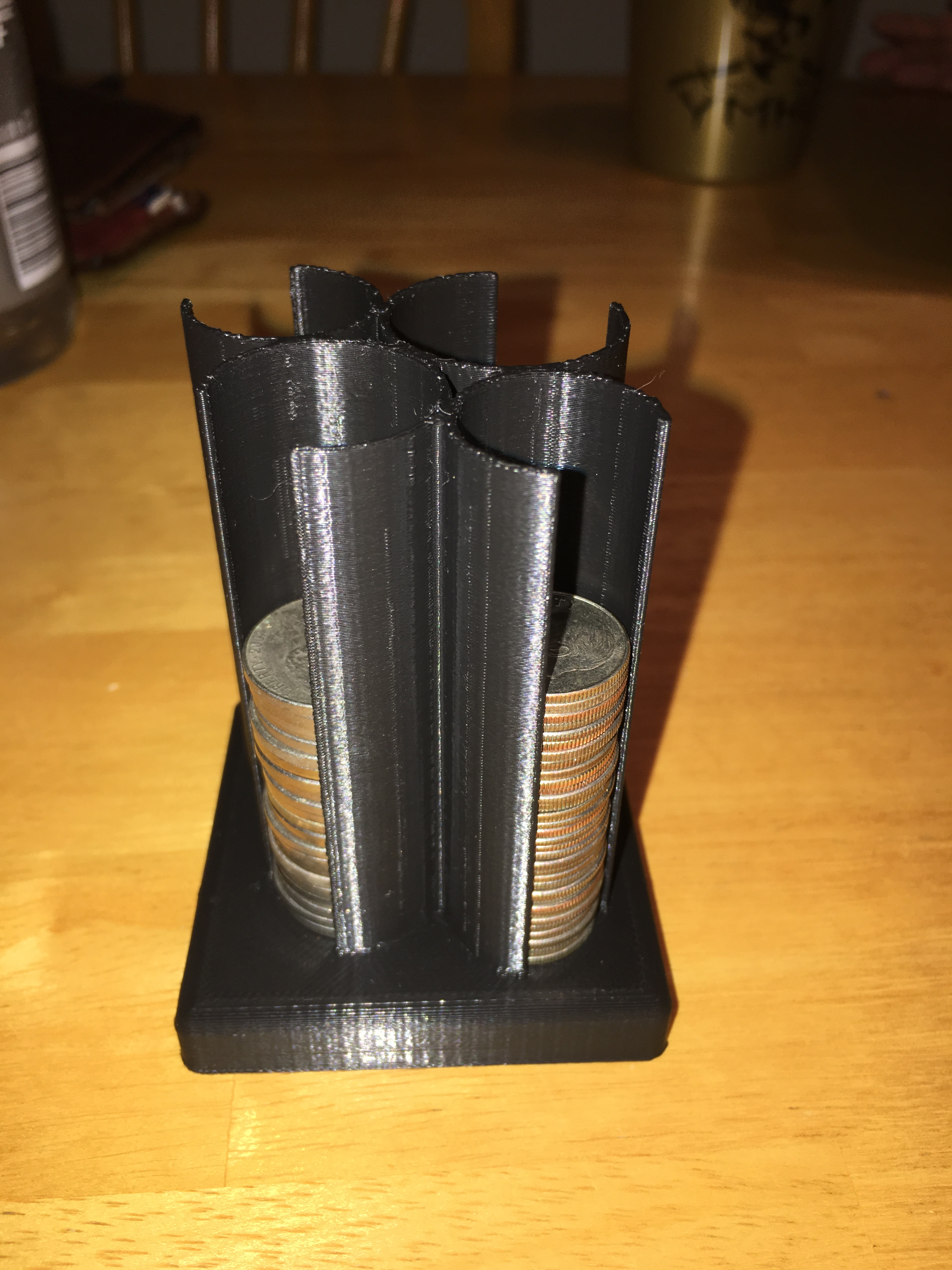
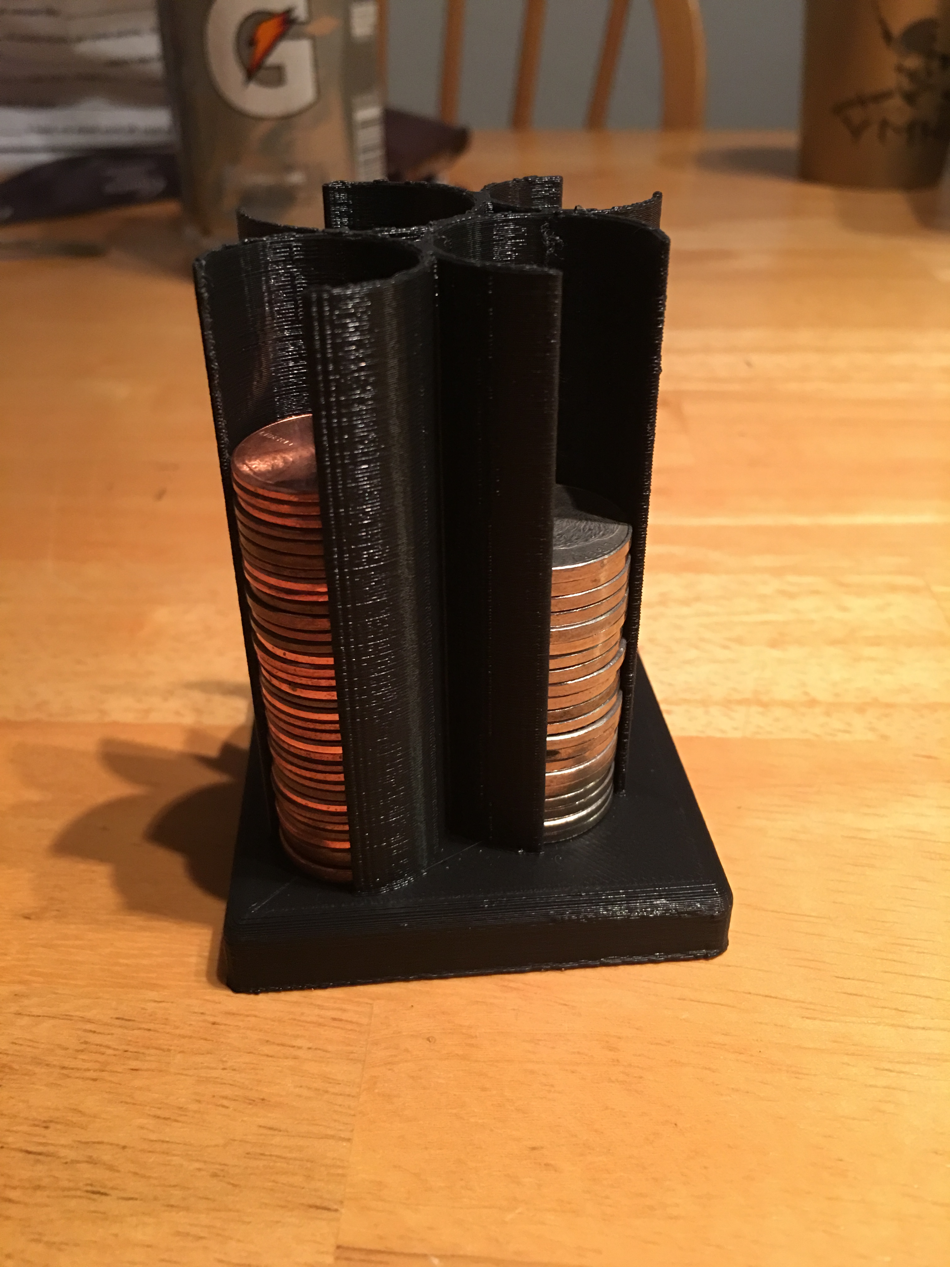
The final step in my fabricating for a function project went really well! I didn’t have to edit my model at all in Meshmixer or DREML, and the only things I changed other than the default settings in DREML was to uncheck the generate supports box and to make my design print with medium quality (only because the walls of the coin holders were only 2mm thick so I wanted to make sure they didn’t come out as spaghetti). Luckily, I started the printing process early and sure enough, on my first attempt at printing, the printer malfunctioned and half of my print air printed. After determining that the structure of my model was not the reason for the air print, I reprinted it and came back the next day and it came out good. Here are some photos of my print in use with coins:
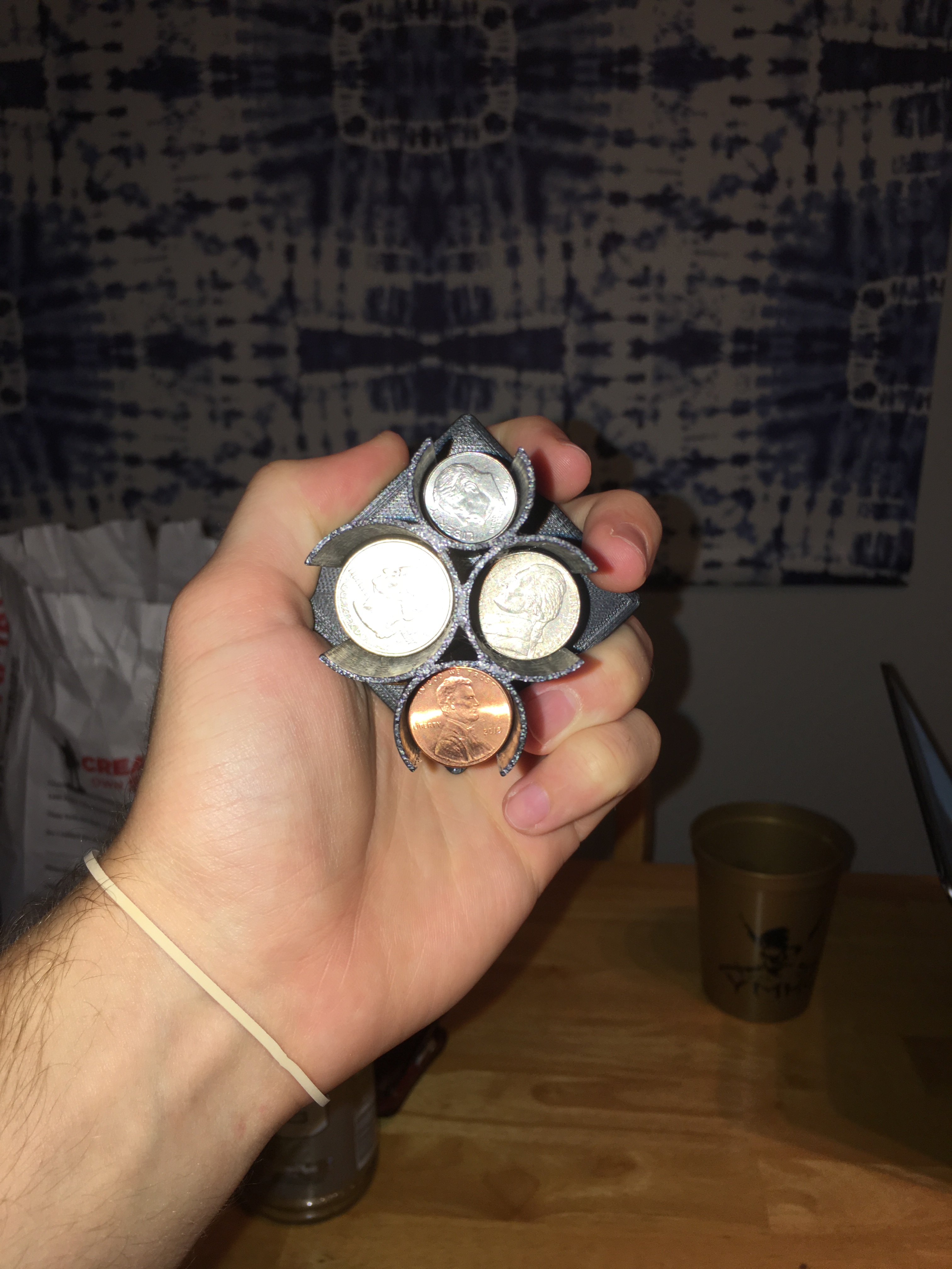
As you can see, the holes I made to put your finger in to get the coins out are small enough so even if the model is turned sideways, the coins still stay in place and don’t fall out.
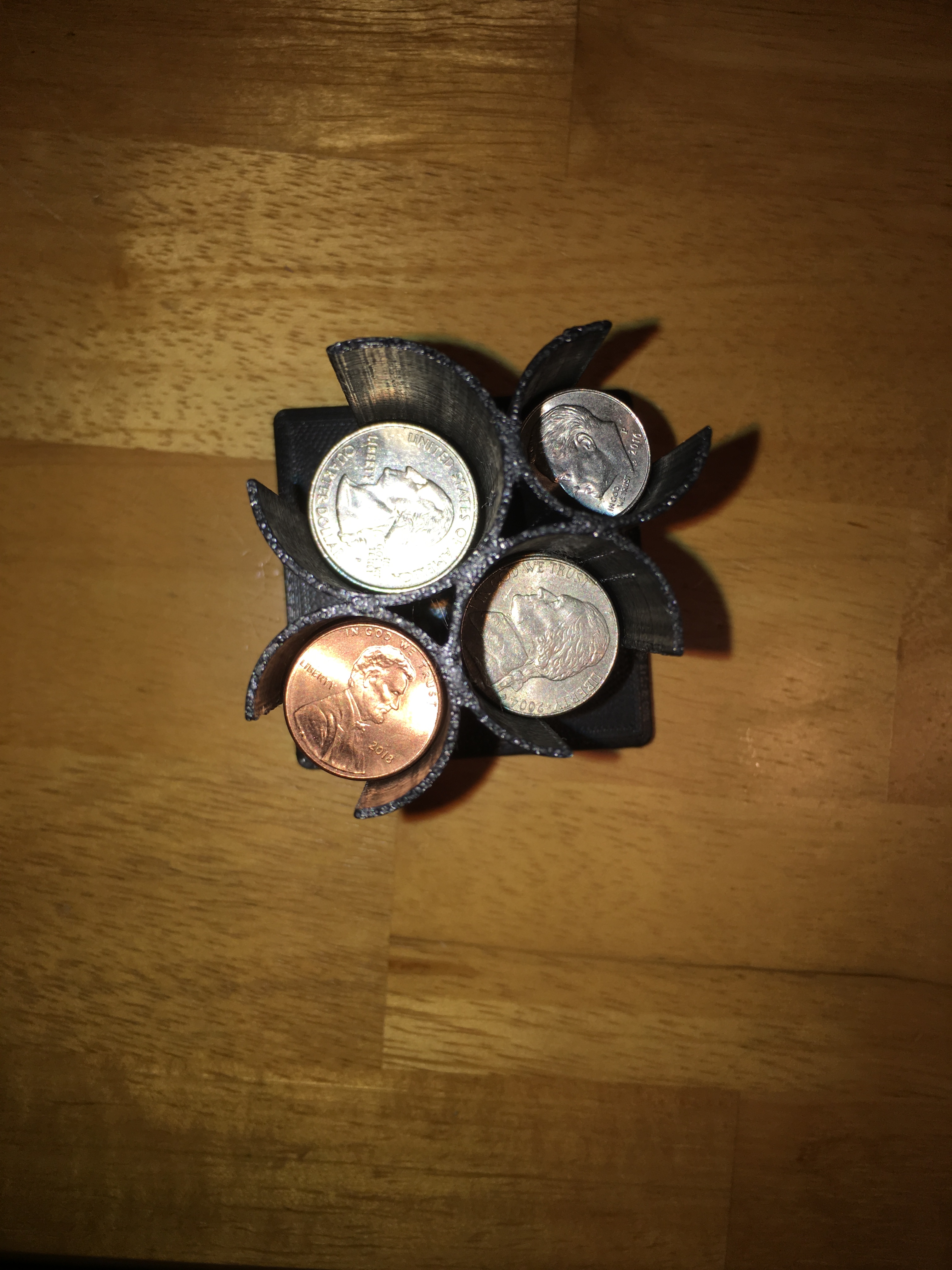
I think the reason my print turned out so well is because of the precise measurements I used while creating my model. The 2mm thick walls were just thick enough to be stable yet still thin and the 1mm larger hole than each respective coin was the perfect size to allow the coins to slip in the holes yet not jiggle around or fall out. Overall, I think this project turned out very well and I’m happy I now have something cool to put on my desk to hold my coins. The process of 3D printing that we learned in class is definitely something I will revisit in the future if I ever have any ideas of things I can print to solve a problem or just to make something cool.
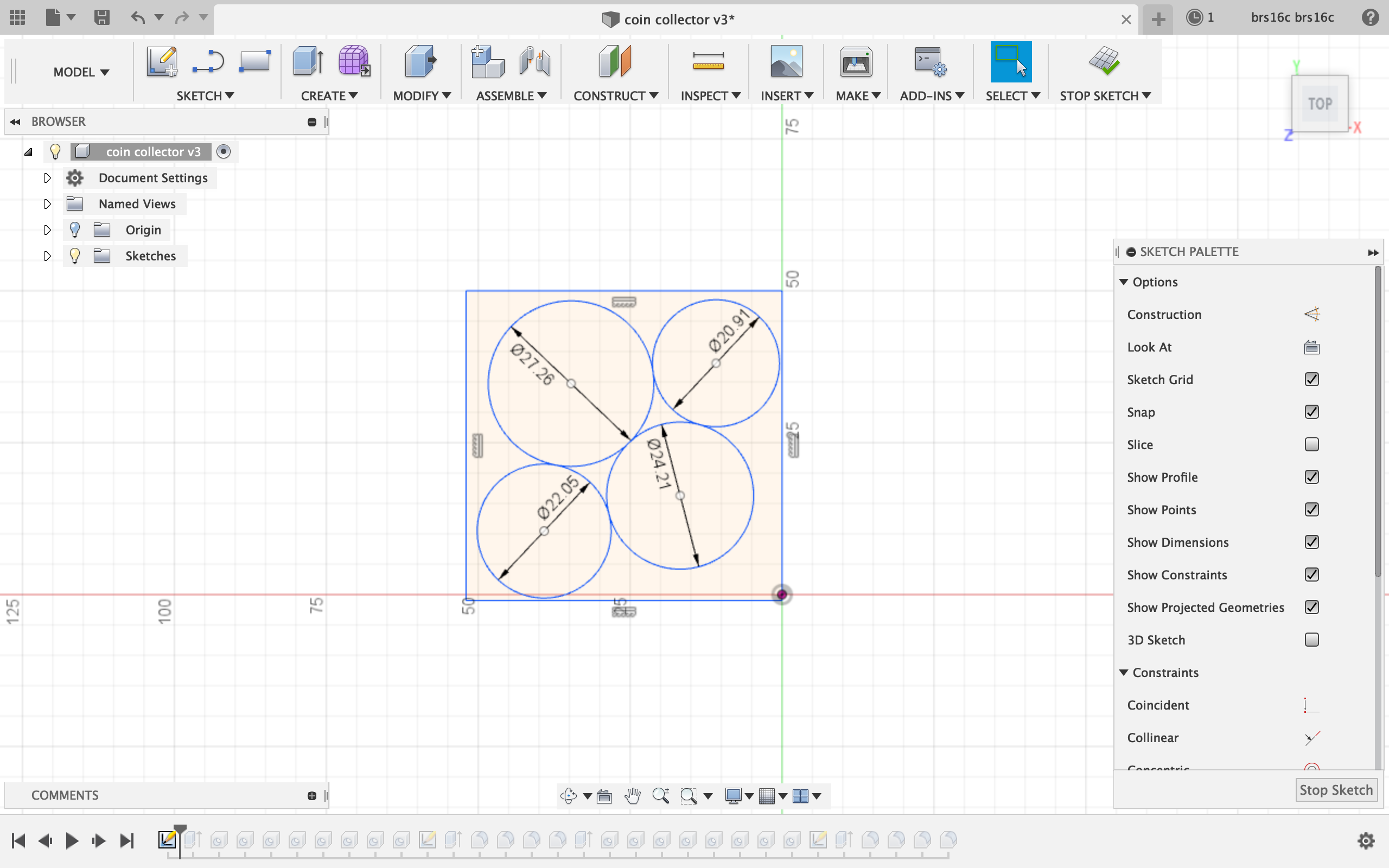
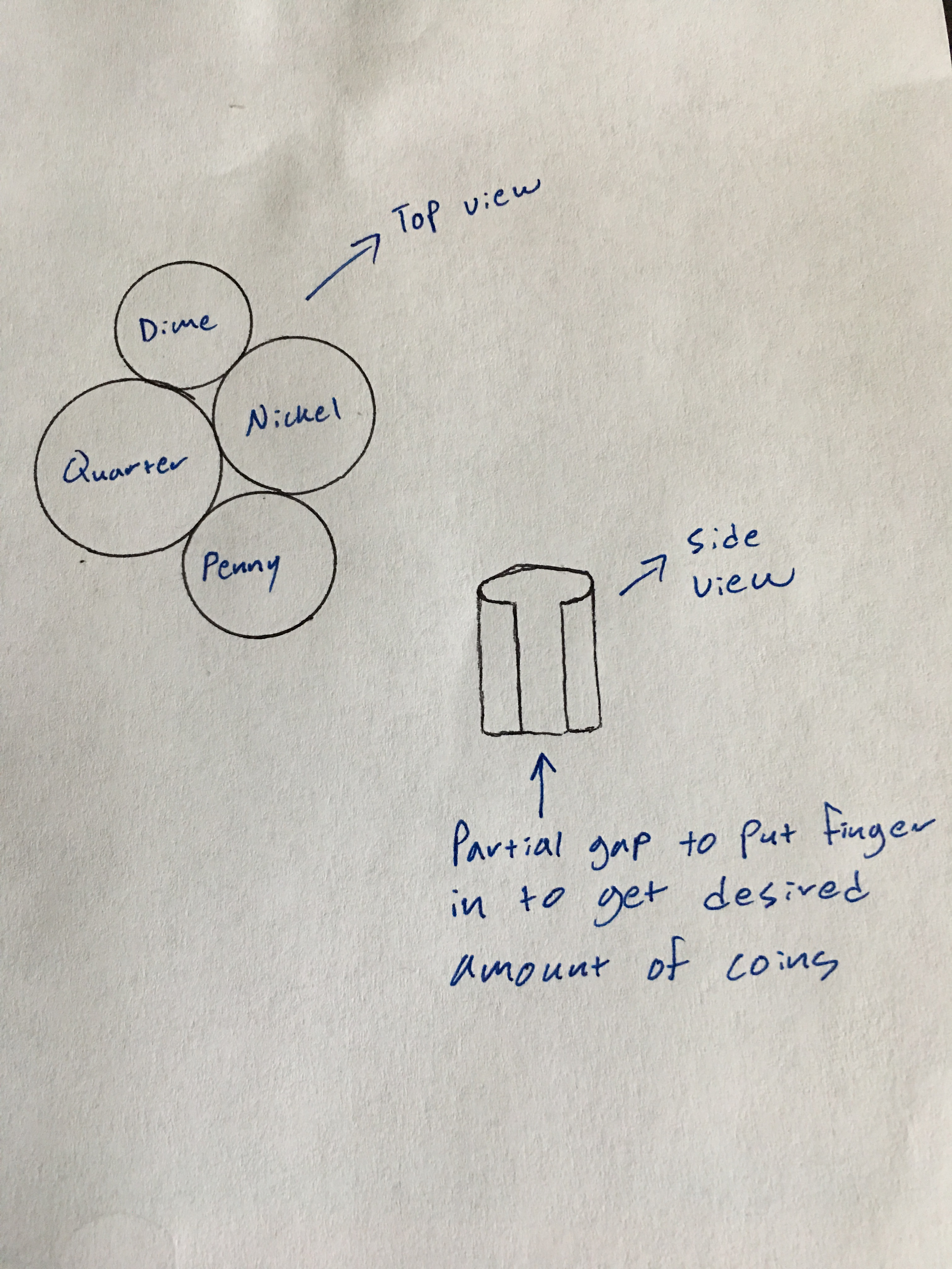
For this assignment, I modeled my coin organizer idea that I described in my fabricating for a function part 1 journal entry. I think my model came out very well and I learned a lot from the process of constructing this model. The first thing I did was research the sizes in millimeters for the 4 coins. I found that the penny was 19.05mm, the dime was 17.91mm, the nickel was 21.21mm, and the quarter was 24.26mm in diameter. Because I wanted the casing to be strong enough to support the coins, I knew I wanted to make the walls 2mm thick. So I made a sketch including 4 circles which were all 3mm larger than their respective coins.
Top left: Quarter, Top right: Dime, Bottom left: Penny, Bottom right: Nickel
The only difficult part in creating this sketch was positioning the circles to be touching each other, but not overlapping. To make this happen, I had to zoom in pretty far in order to fine-tune the position of each circle. Another issue I ran into was that I wanted to create a break in the sketch in order to make a place to put your finger to pull coins out, but I could not find a tool to do this. Under the sketch tab, I tried both the trim and break features, but neither of these tools would break my circles. I got around this obstacle by deciding the extrude all 4 circles and create two holes: one on the middle where the coins will fit, and one partially in the side of each circle which would create a place for your finger to fit.
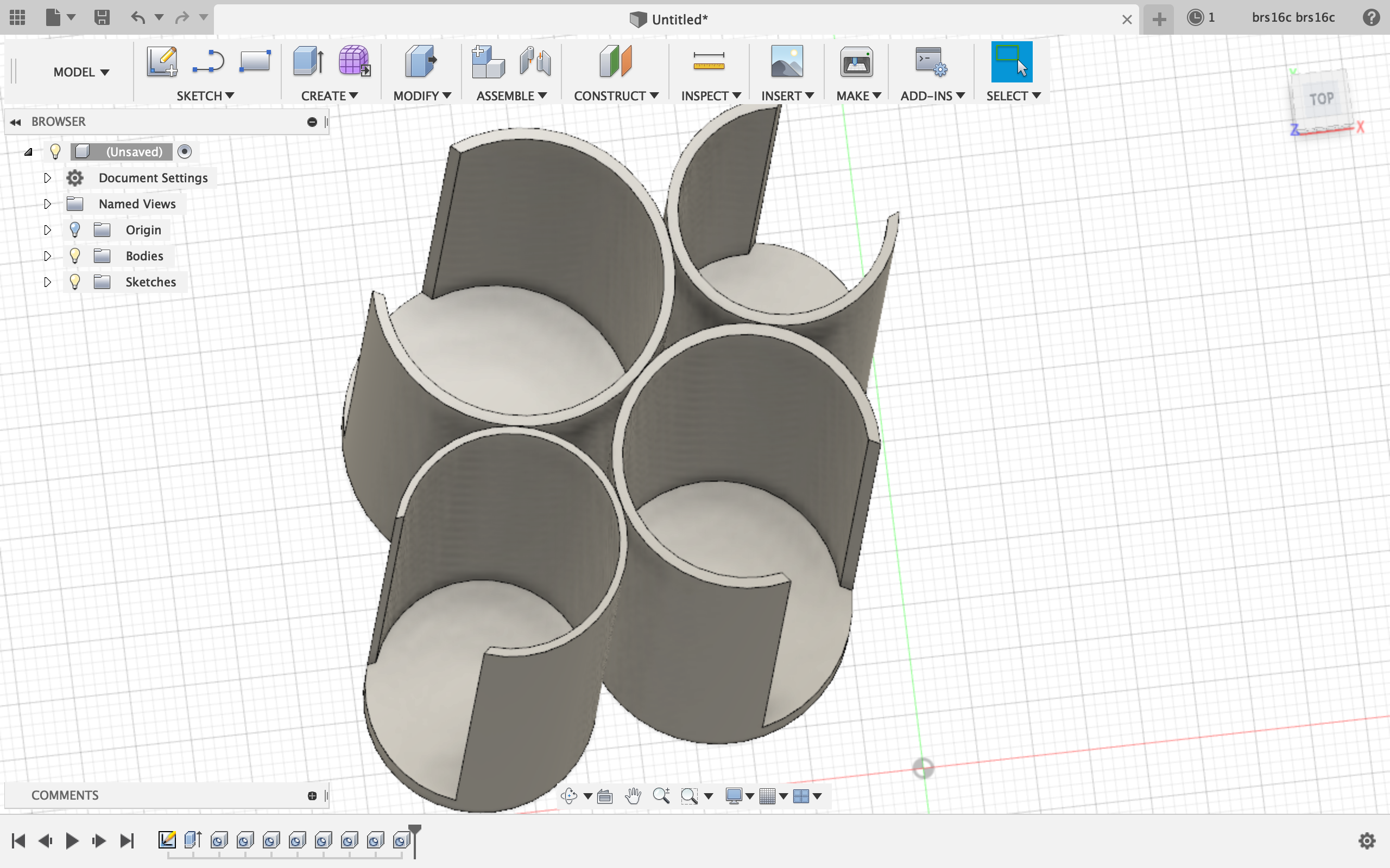
This is what it looked like when I followed the process described above. I made the hole in the center 1mm bigger than each respective coin which would give each hole a 2mm thick wall which I thought was sufficient enough to be stable while still leaving 1mm of room for the coins to fit. (I accidentally made the penny wall 1mm instead of 2mm, but I fixed this before creating the final product.)
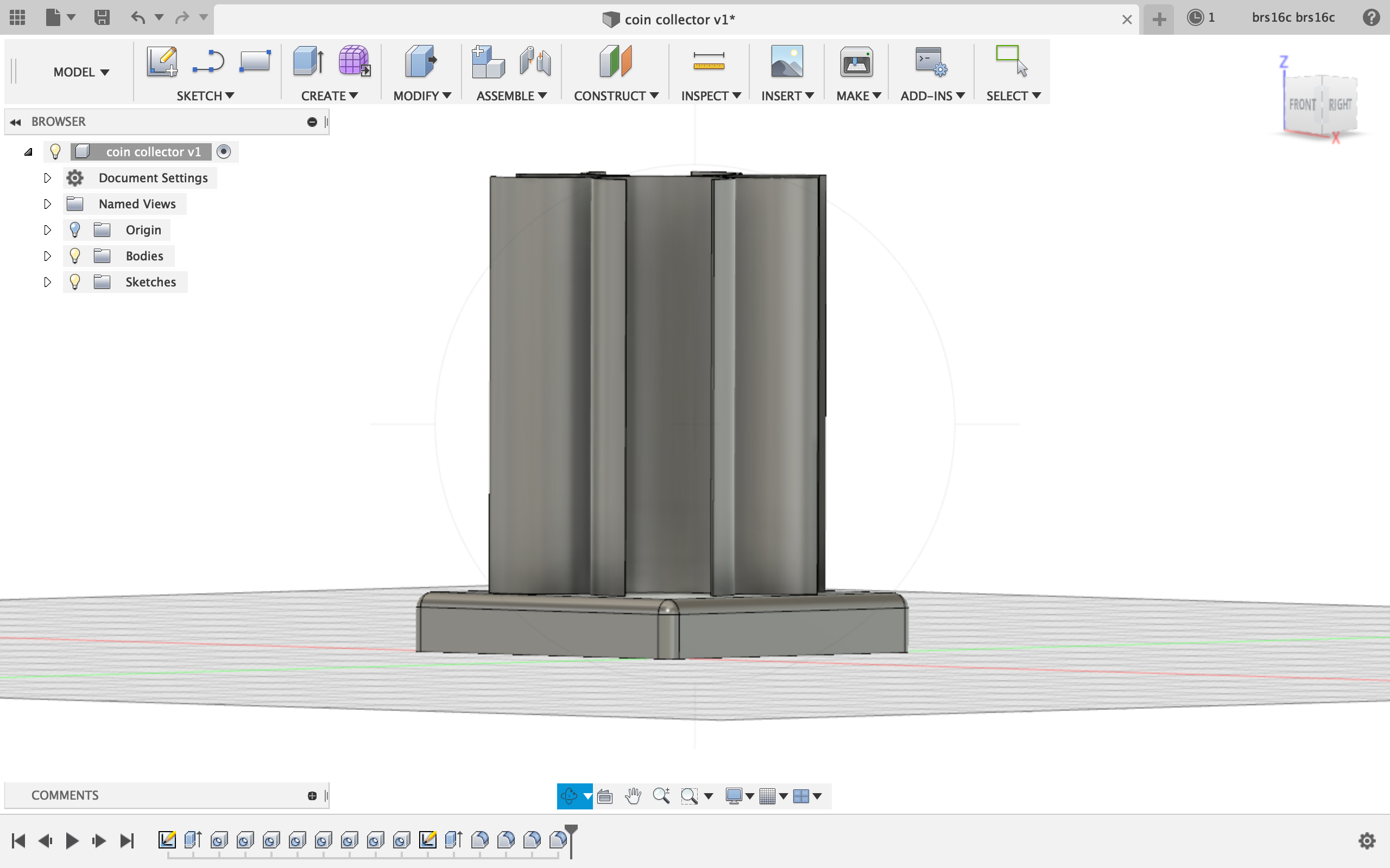
After this step, all I had to do was rotate to the bottom and create a sketch of a rectangle 60x60mm which would act as a base for the coin holders. I then extruded the base 10mm in the opposite direction and used the join feature to join the 2 halves.
This is what that step looked like. I also used the fillet feature to round the edges a bit to make a more attractive base.
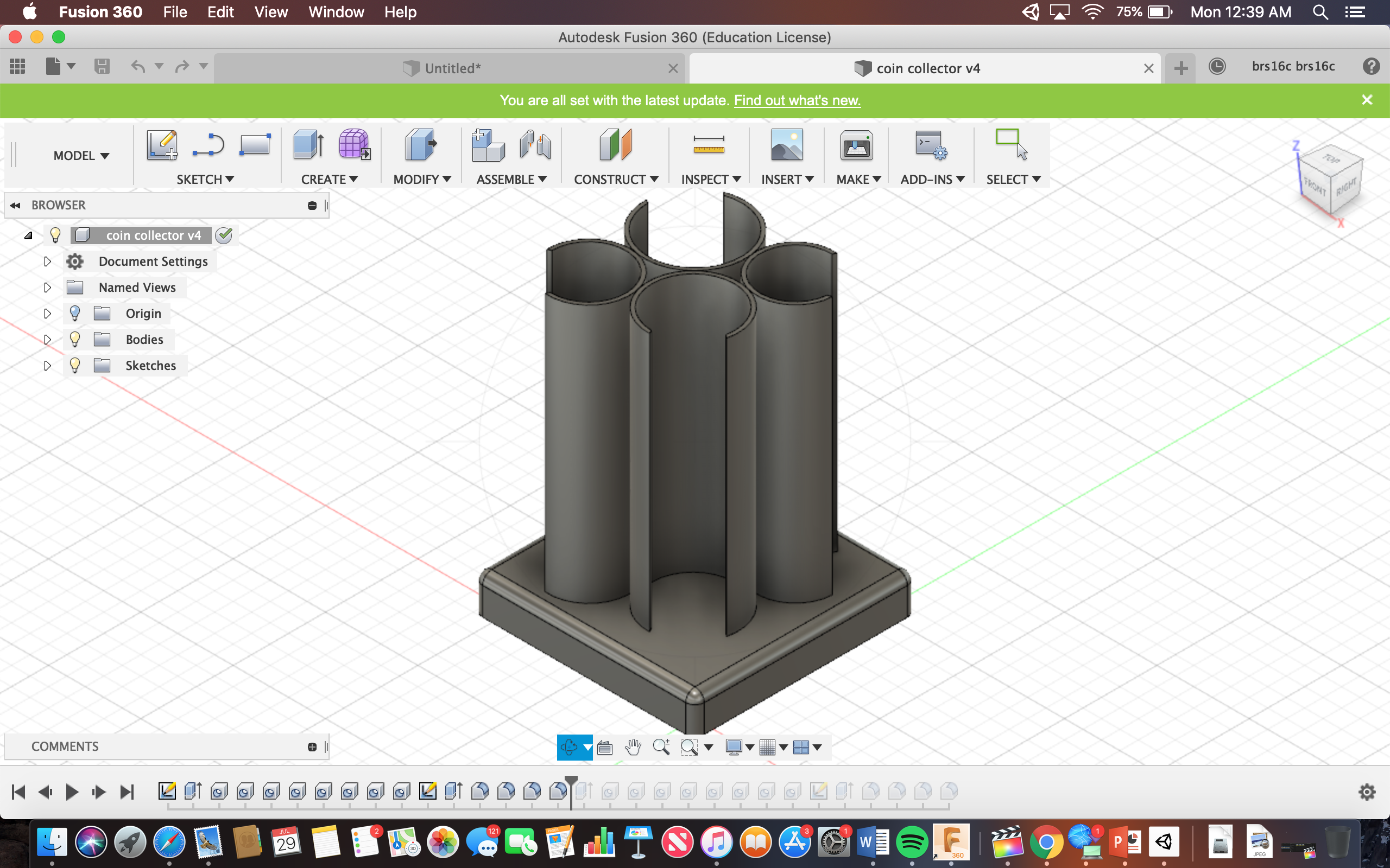
Here is the finished product:
The holders are 75mm deep which can hold at least 27 of each kind of coin.
For the raspberry Pi project I am part of group A which means I will be taking my assessment grade for this project. However, if I were to create something with the raspberry pi, I would like to download the OpenELEC operating system to my pi and Create a device that can turn any tv into a smart TV. Once this is finished, I would connect the pi to the internet via an ethernet cable and connect the pi to the TV via HDMI. At this point, all I would need would be to plug in the Pi to power and connect a mouse/keyboard via USB which would be used to control the Pi and select which movie/TV show I would want to watch. The primary reason I would want to create this project is because my grandmother has only been using a TV that can get channels through antennas for as long as I can remember. For some reason she refuses to pay for cable TV and had never upgraded to a smart TV. With my RaspberryPi creation I could solve her problems and finally give her something good to watch!
The picture above is what I would do with the RaspberryPi. However, instead of OSMC I would install openELEC because of how easily accessible many dangerous features in OSMC are and instead of using a computer monitor I would use a TV.
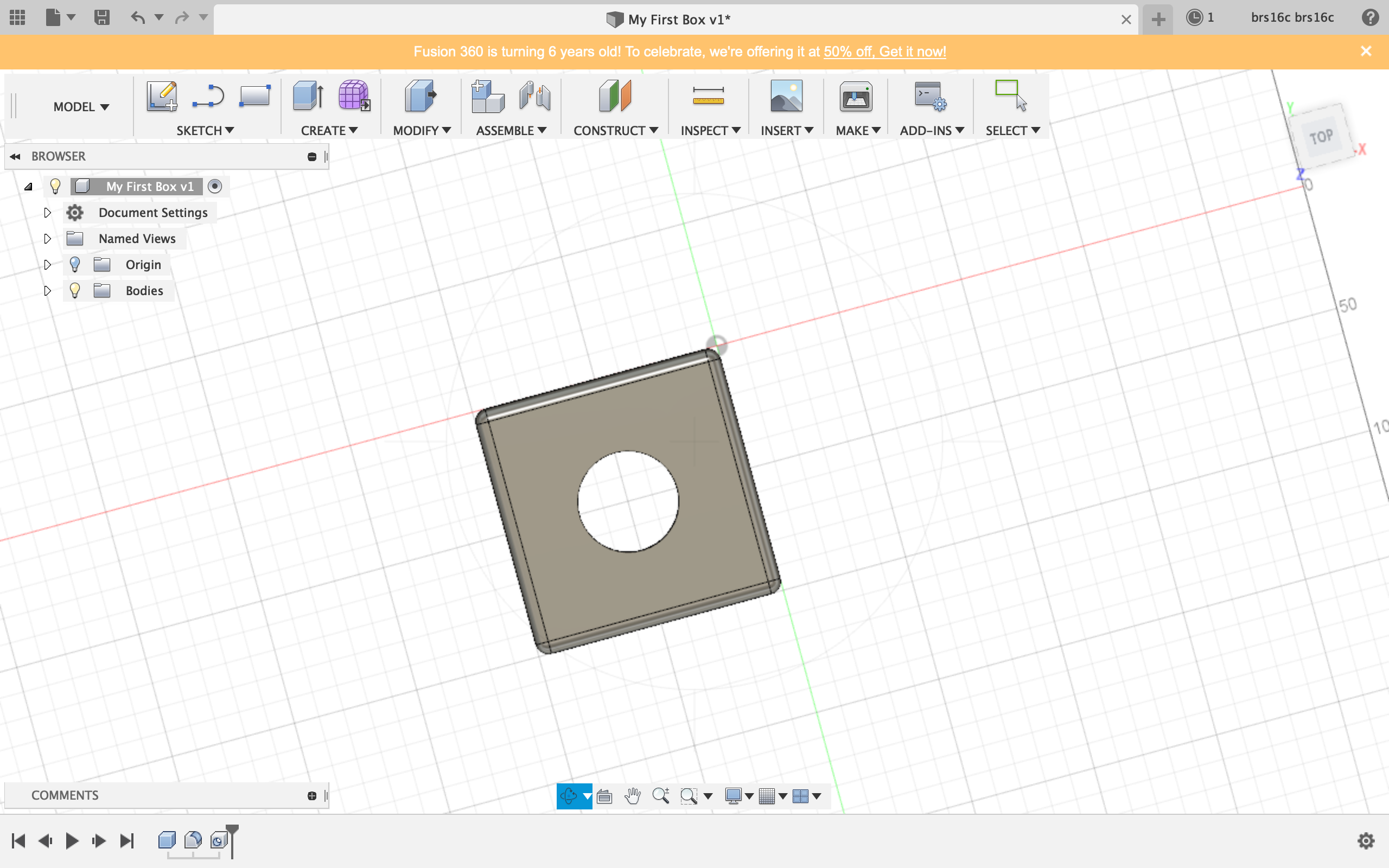
I found fusion 360 to be much easier than free cad just because everything is much easier to move around and all of the faces were clear. One of the main difficulties I found when modeling in free cad was that it was hard to get a grasp on the full 3D picture of your model and there were so many function. Fusion 360 was much easier to understand and after doing the tutorial shapes (box and lampshade) I started to get the hang of it.
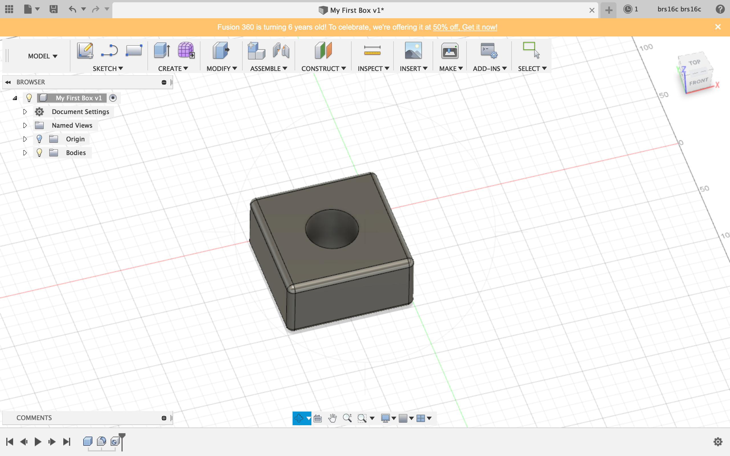
Shape 1: Box
I found this shape to be very easy to create as the tutorial walked me through the process.
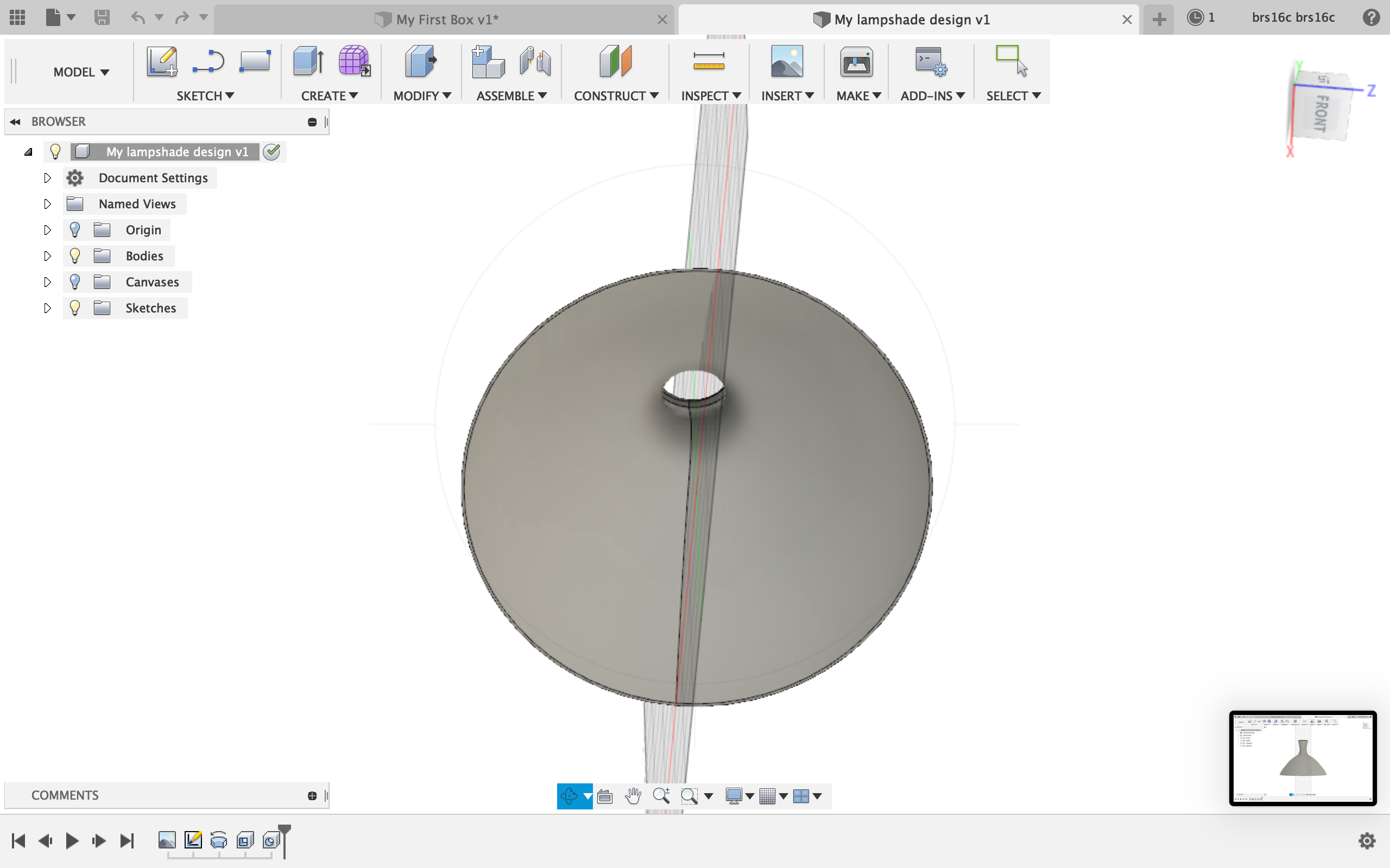
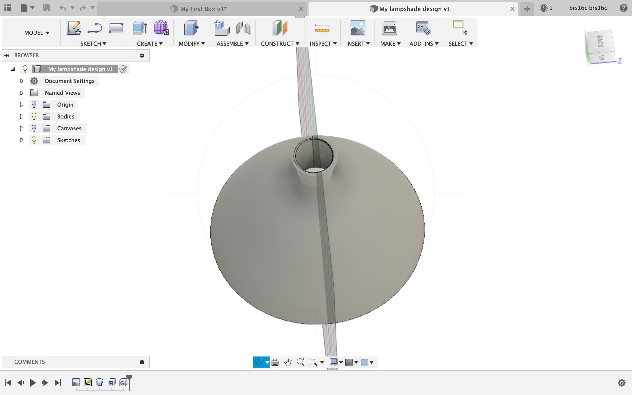
Shape 2: Lampshade
I created this lampshade using the line and spline tools in the sketch section and then rotating the lampshade around an axis to create the full shape. The last step to the lampshade was creating a hole through the top so it would be hollow. I changed the default mewl material of the lampshade to a carpet material .
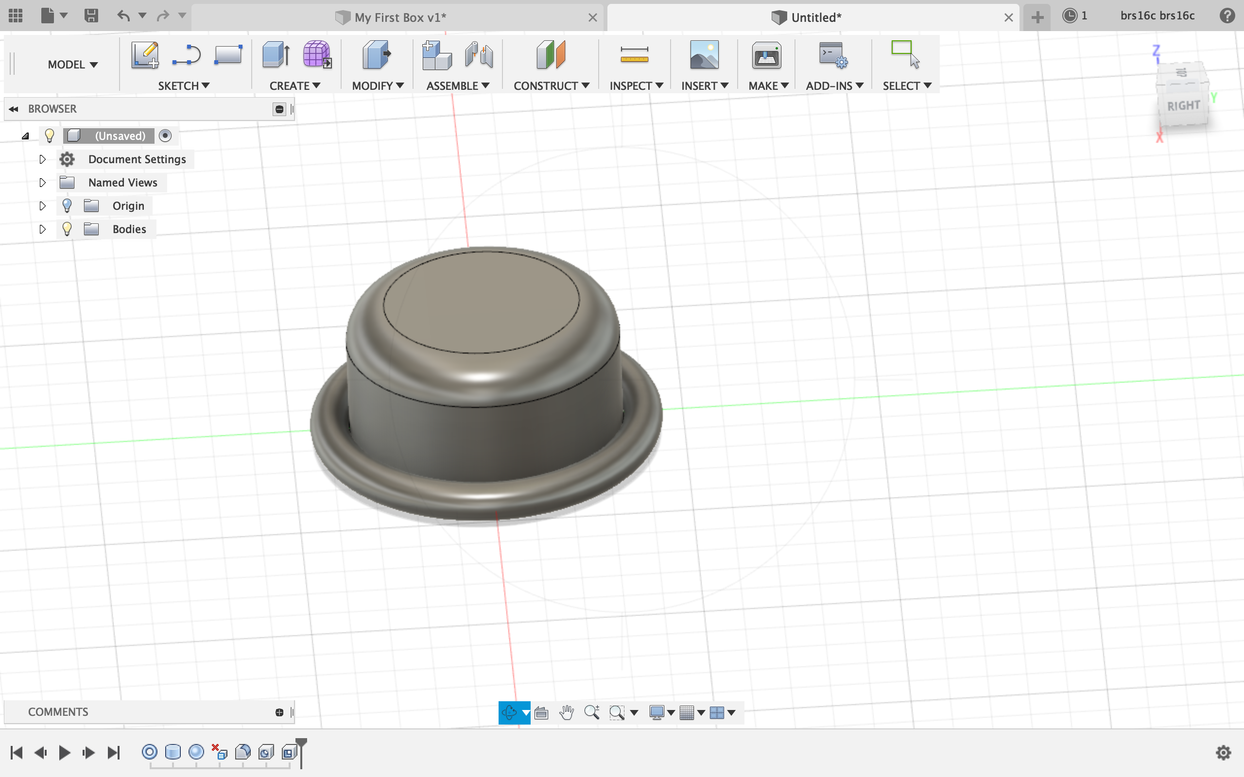
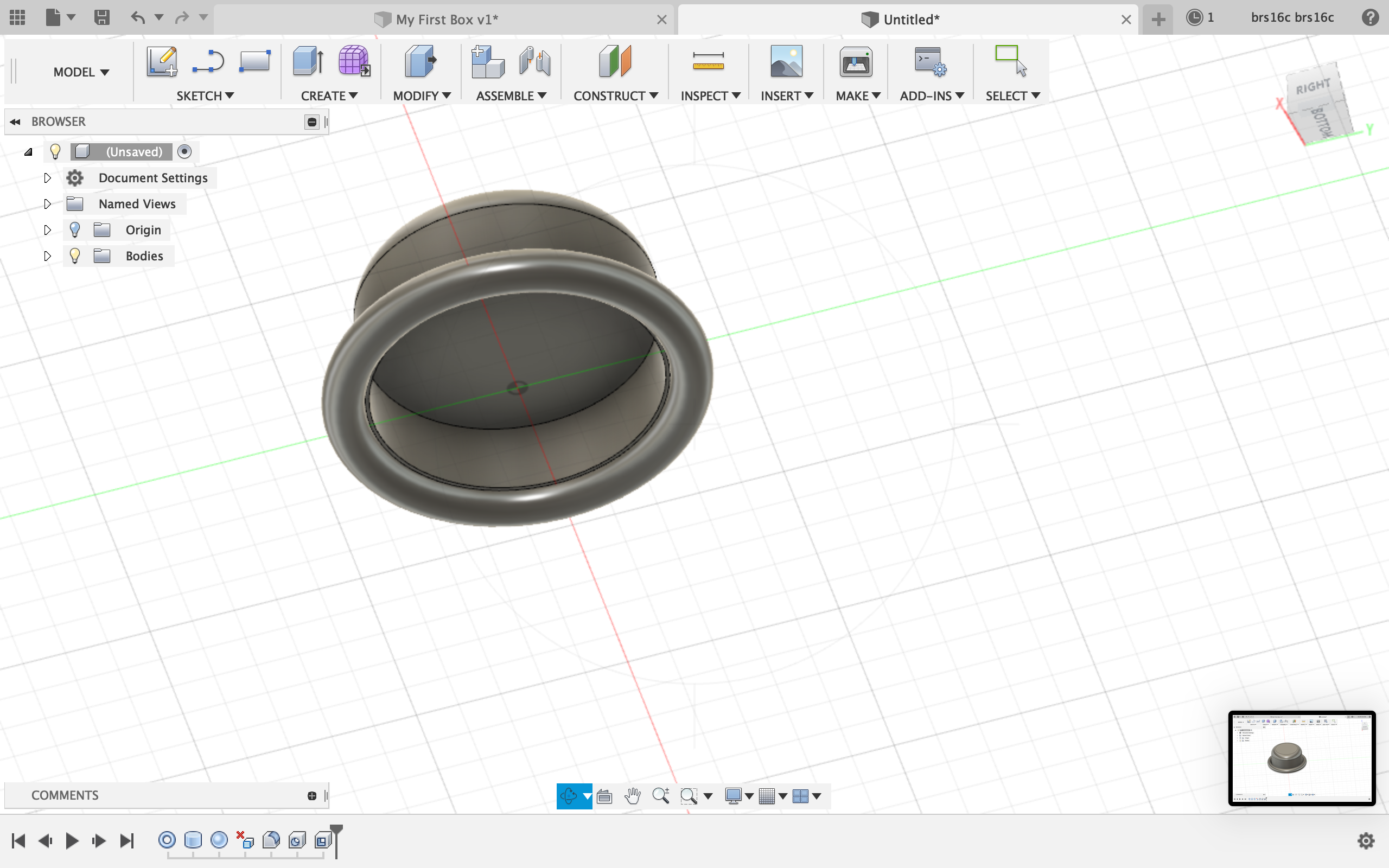
Shape 3: tophat
Here is my tophat. The only issue I had with this shape was figuring out how to make the torus hollow to create the brim. I knew I had to use one of the functions under modify. I tried using press/pull, fillet, shell, and draft, but none of these functions seemed to work. To create the rounded top of the hat, I used the fillet functions which created rounded edges of the cylinder.
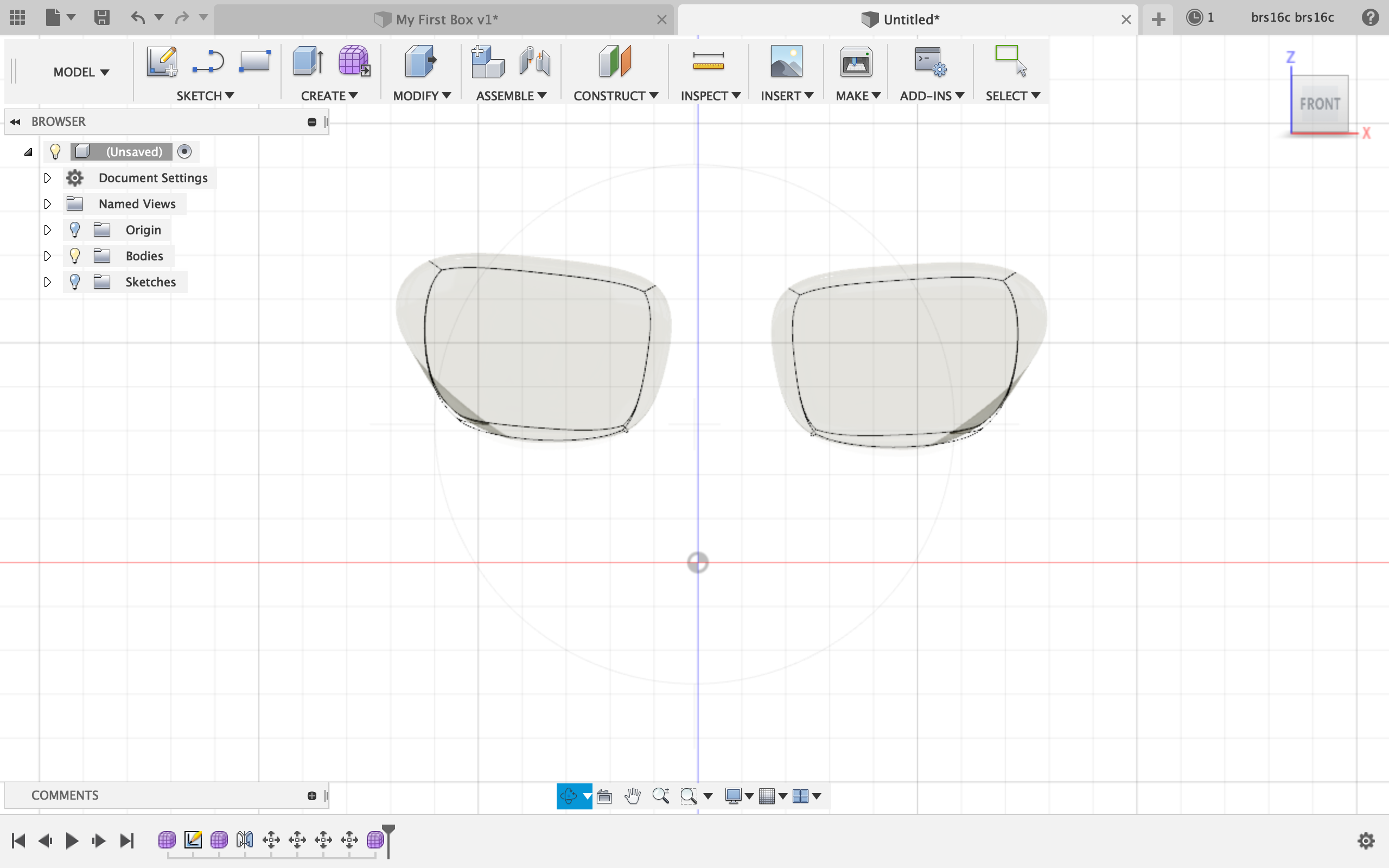
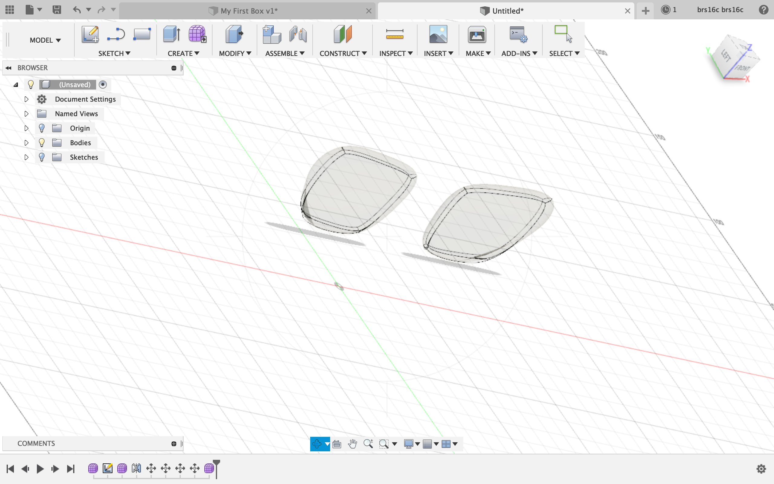
Shape 4: Aviators
The aviators were really difficult for me to create. To create the lenses, I went to create form under create and made a thin box. I then modified the box to be in the shape of a lens by pulling and dragging the edges and surfaces of the box. I then mirrored the shape across the axis to create the other lens. Unfortunately, I was having a really hard time creating the bridge between the lenses as I could not find a shape that I could mold into the bridge shape. However, I played around with the material and made the lenses glass which was cool.
All in all, Fusion 360 was easier than free cad, but making complicated shapes like the aviators was difficult for me since I was absent the day Lucas explained Fusion 360 to the class. However, I am happy with what I was able to get done by following the tutorial and playing around with the interface.
for this assignment, I would like to create an organizer for my change that I can put on my desk or in my car. The reason I would like to create this is because I have a lot of loose change as a pizza delivery driver and I don’t know where to put all of my change. Plus, I think this creation would allow me to actually get use out of the change I collect since I just have it laying around and if it was sorted, it would be much easier to access and use. Like I explain in my video, I will have 4 separate compartments within my change holder, each with a different size so that a different coin can fir in each compartment. The coins will stack up within the compartment and you can pull them out as needed when making a transaction. (Since WordPress is not allowing me to include a video file in this blog post, I will include my video as part of my submission on canvas.) Also, I know that I am completing this assignment late, but I have been very busy with work and have been dealing with some family issues that have prevented me from staying up to date on my assignments. However, I still plan on completing all of the assignments and will complete them to the best of my ability. Here is a sketch of what I plan to make:
At first, Freecad was extremely confusing and difficult to work with. By the end of this assignment, it was a little less confusing, but still preeeetty difficult to work with. The first portion of this assignment was simply completing the tutorial for freecad. Unlike every other tutorial I have ever completed in my life, this tutorial was super hard. But, with professor Von Hollen’s help I was able to complete it and make this shape:
To make this shape I simply followed the steps in the Freecad tutorial.
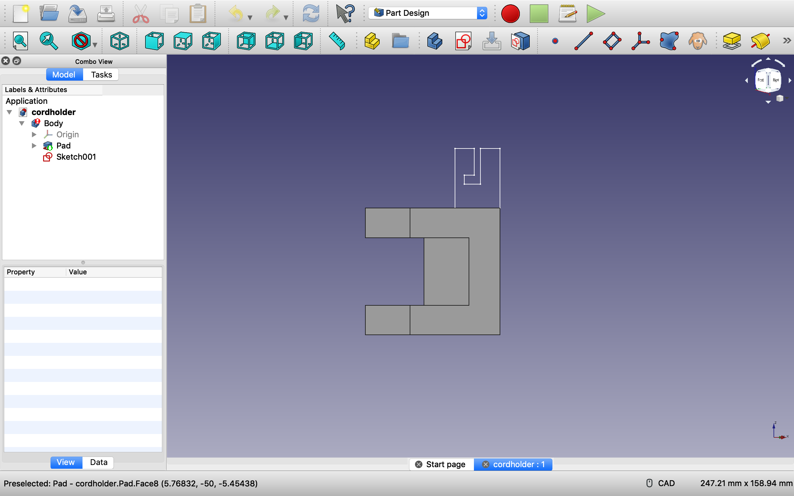
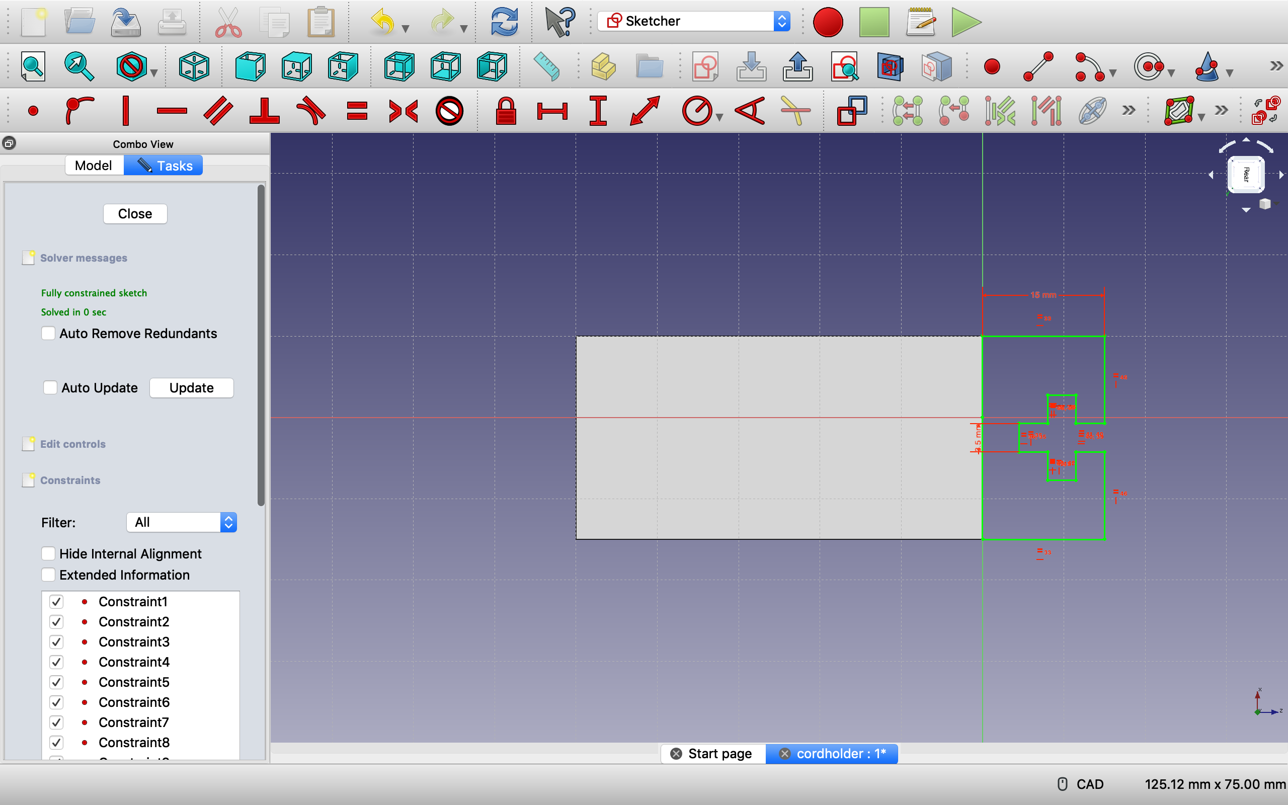
The next task for this assignment was to create an object that could clamp onto a desk and hold a wire of some kind in it. Using the measurements of the desk I obtained in class and a Mac charger wire, I was able to construct the body of the object that clamped onto the desk.
The desk measured to be 26.6 mm in height so the inside area of the clamp is 26.65 mm which should fit snuggly on the desk. Also, on the sketch of the cordholder, I made the entrance and tunnel way 3.5 mm wide because the cord that I measured was 3.14 mm wide.
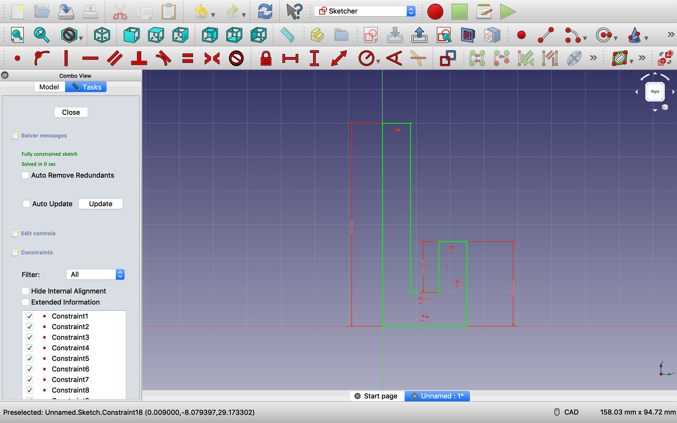
However, after completing this step I ran into some issues. After flipping the body around to the back and creating a new sketch, I sketched an object that would go on top to hold the cord. this cord holder would constructed in an L shaped fashion. However, Freecad was giving me issues and I was unable to complete this step.
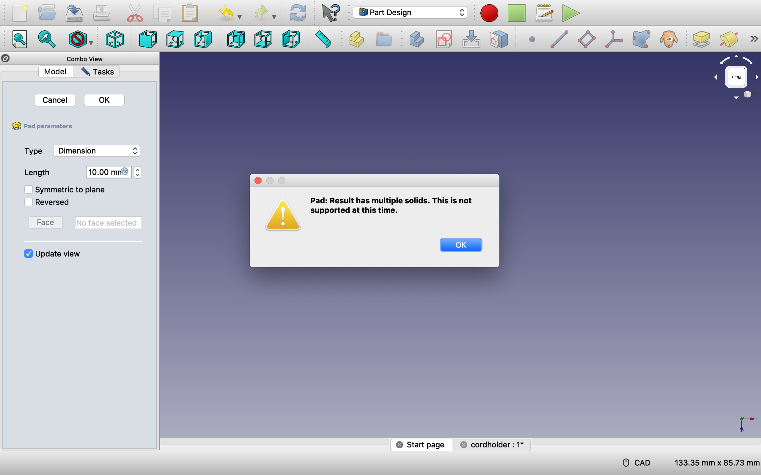
As you can see from the images above, even after fully constraining my sketch and creating external geometry on the back face of my clamp and coinciding my fully constrained sketched object onto my clamp, when I would attempt to pad the sketch it would give me the error message seen above. I was unsure how my sketch had “multiple solids” as I only created one poly-line sketch and made sure to fully connect it. I even tried making different shaped in my cord holder such as a simple square or circle but the multiple solid error message persisted. I also tried creating external geometry on all 4 corners of the back face and coinciding my sketch to all 4 corners like professor Von Hollen did in class. Unfortunately, after my best attempts at this step, I was unable to complete this step as Freecad was not working with me. If it would have let me pad my sketch, I would have proceeded to set the pad of the cordholder as “through all” so that it would cover the full length of the clamp.
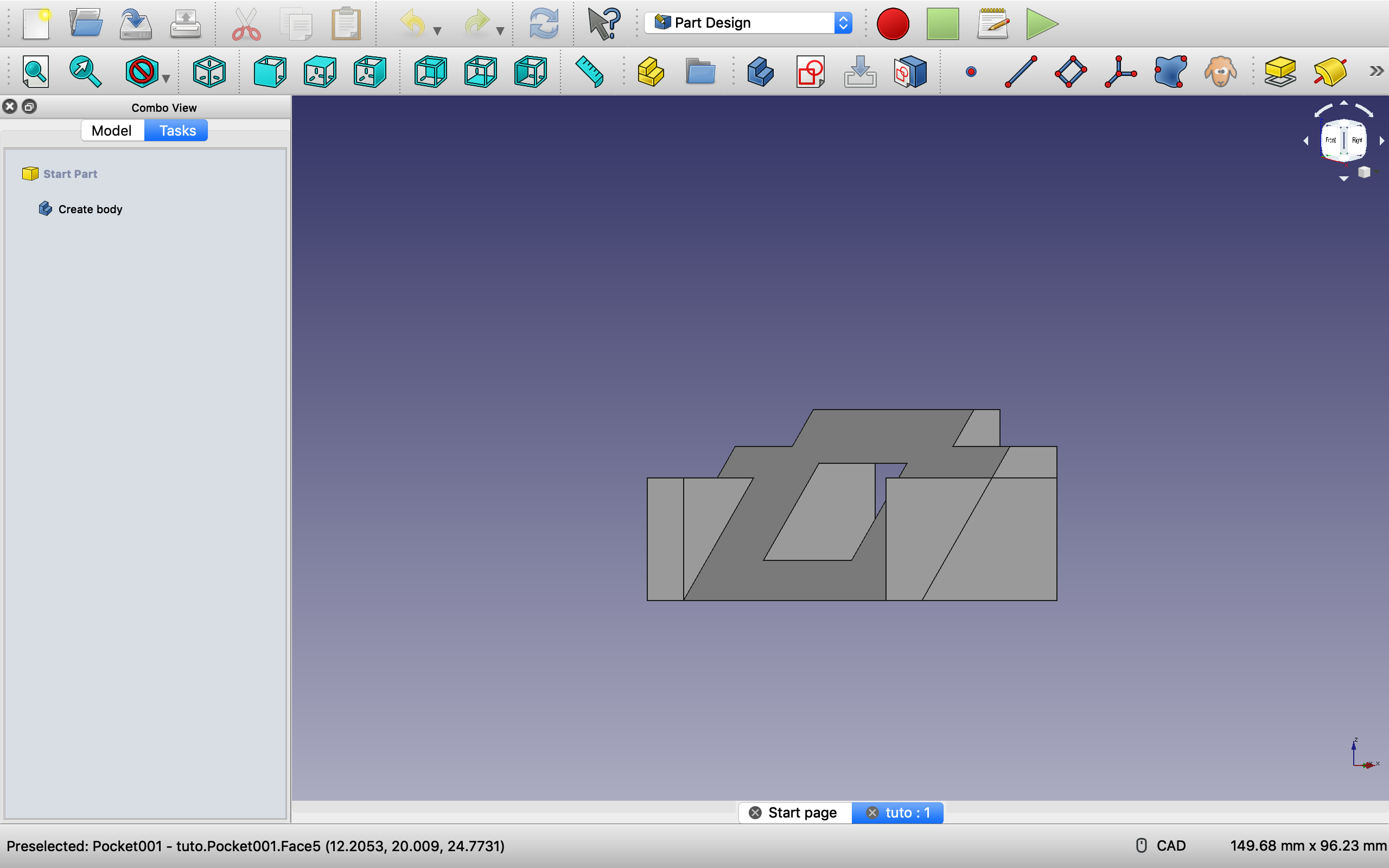
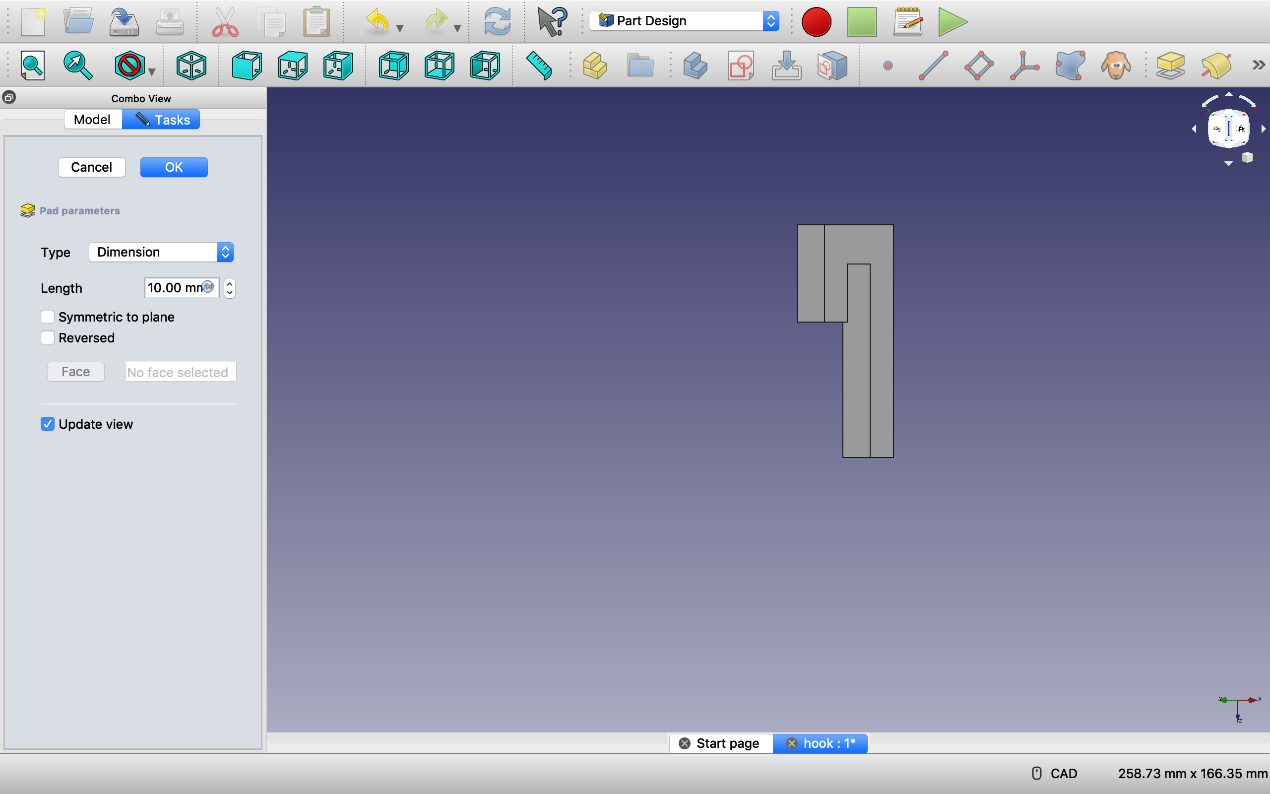
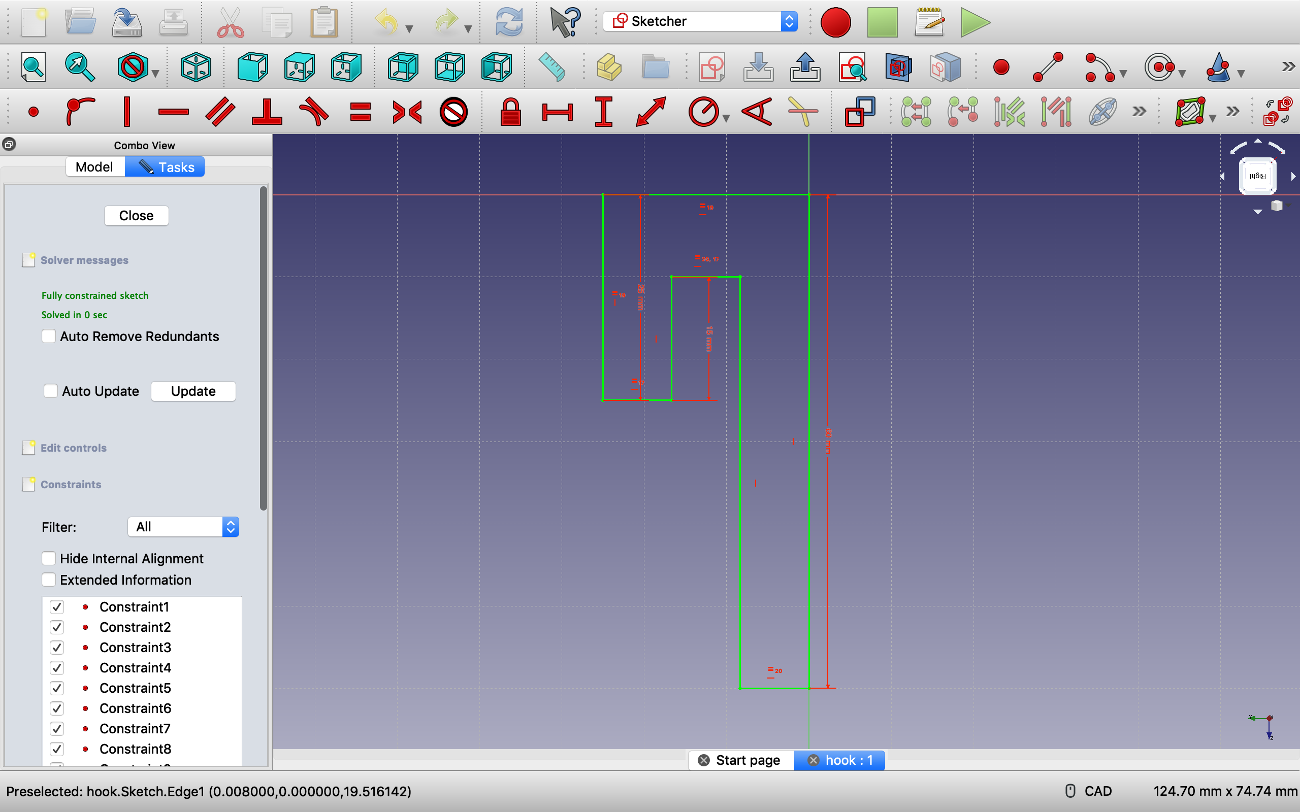
Here is the padded image of one of the sketches, it is a hook shaped object that fits together perfectly and when held , the other half will not fall out because of the hook structure.The bottom half of the hook structure that will fit into the top halfThe top half of the hook structure. Professor Von Hollen would hold the structure along the longest side.
For the third and final part of this assignment, I created a hook-like structure which fits together perfectly. The idea is that the pieces fit together and either way they are held, the bottom piece would not fall out.
All in all, I actually enjoyed using Freecad as it was a challenge. I enjoy taking on challenges like this and usually would not stop until I was completely finished, but after hours of trying to solve the error message in part 2 and finding no online resources as a help for getting rid of the error, I was unable to finish that part.
This assignment was a little tough to get going on since I missed class the day Tinkercad was introduced. Because of this, during the class where professor Von Hollen was demonstrating the more complicated models like the flask and the spoon, I was stuck trying to figure out how to make my egg hollow. By the end of our class on Monday however, I was able to finish both the PVC pipe model and the hollow egg. Once these were finished, I started to get the hang of it and I was creating the models fairly quickly, each one taking 15-30 minutes (besides the aviators, that one took forever). Anyways, here is a look at the 7 models I was able to create using Tinkercad.
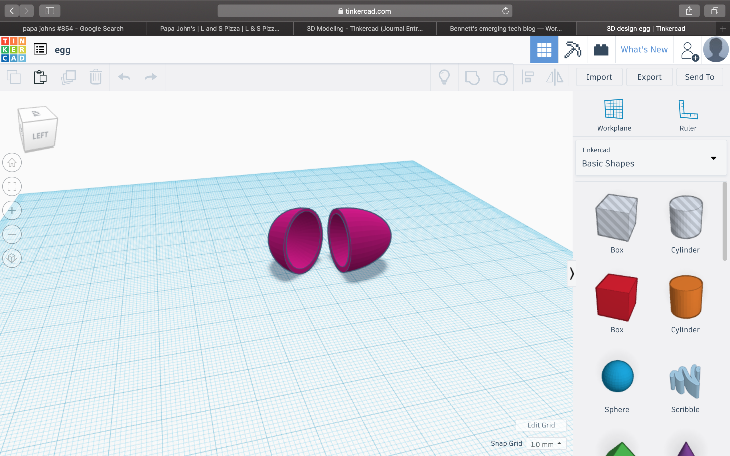
#1: Hollow egg
just a pink, hollow egg
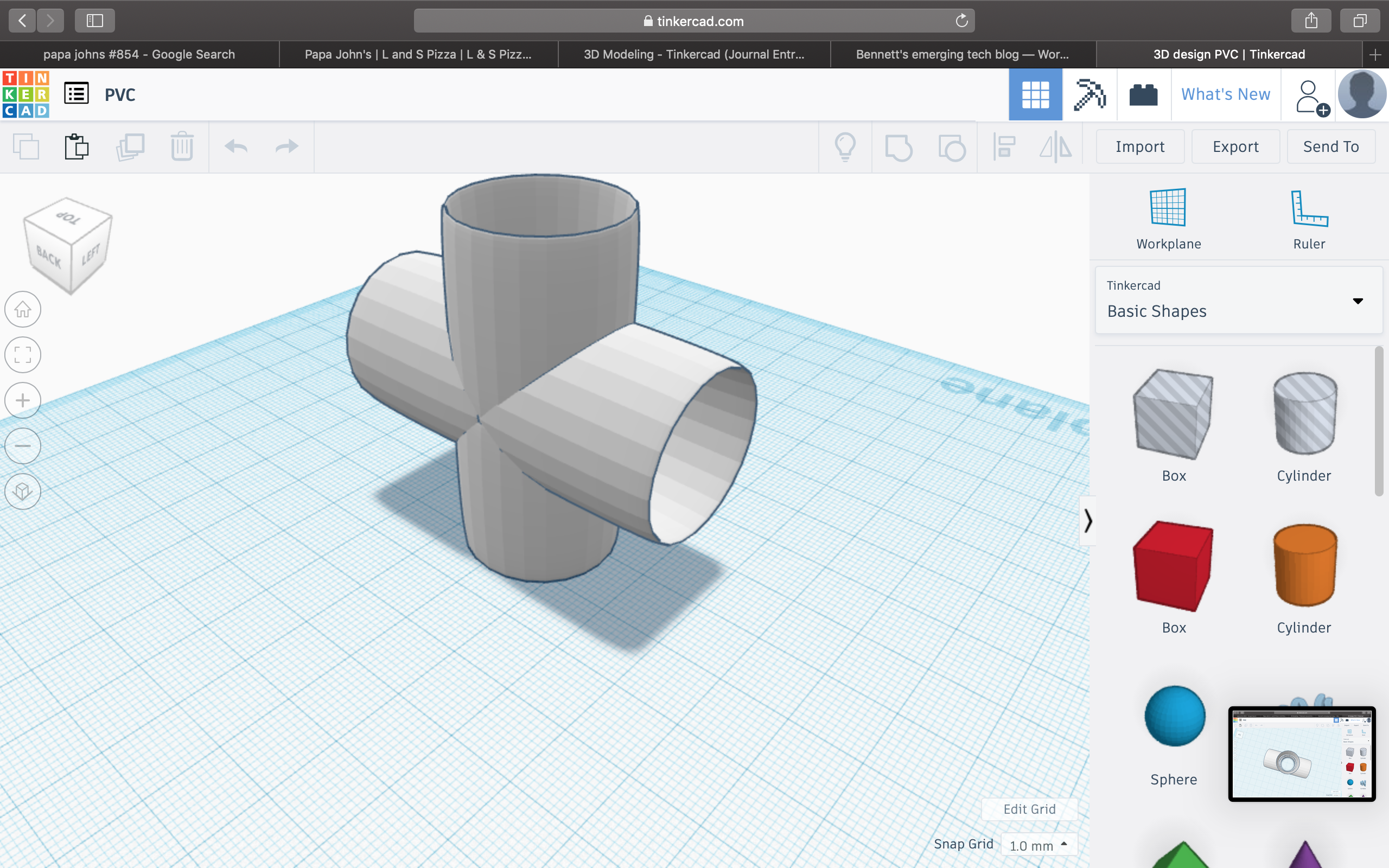
#2: PVC
white PVC
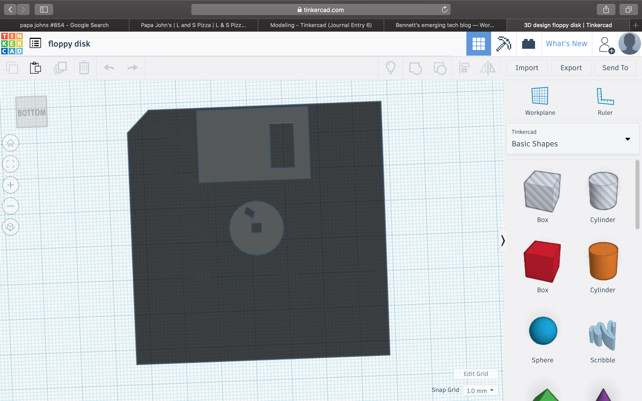
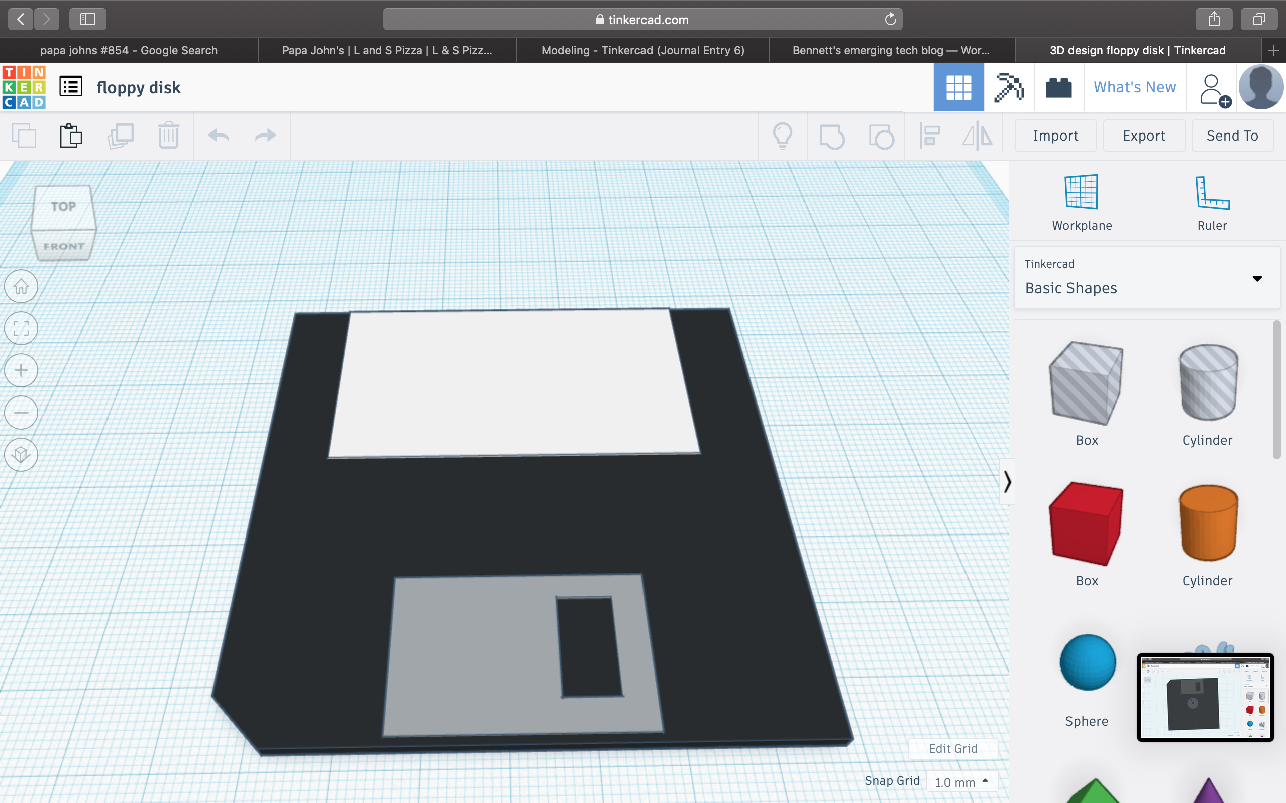
#3: Floppy Disk
2 pictures needed to show the intricacy of this model. As you can see the model has all of the essential qualities of a real life floppy disk.
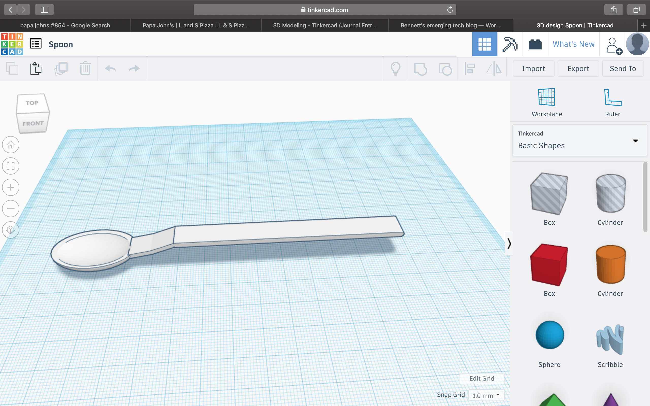
#4: Spoon
A spoon. A device made by man to assist in the process of eating.
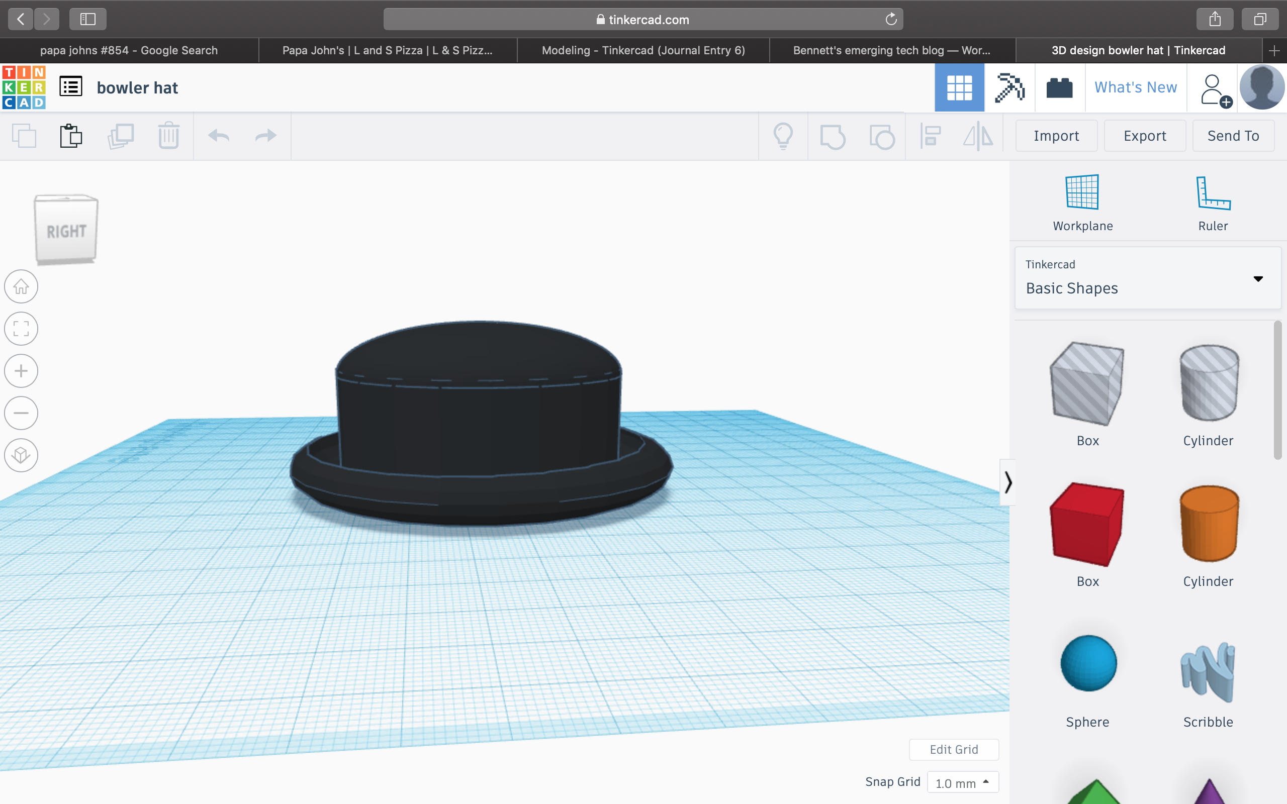
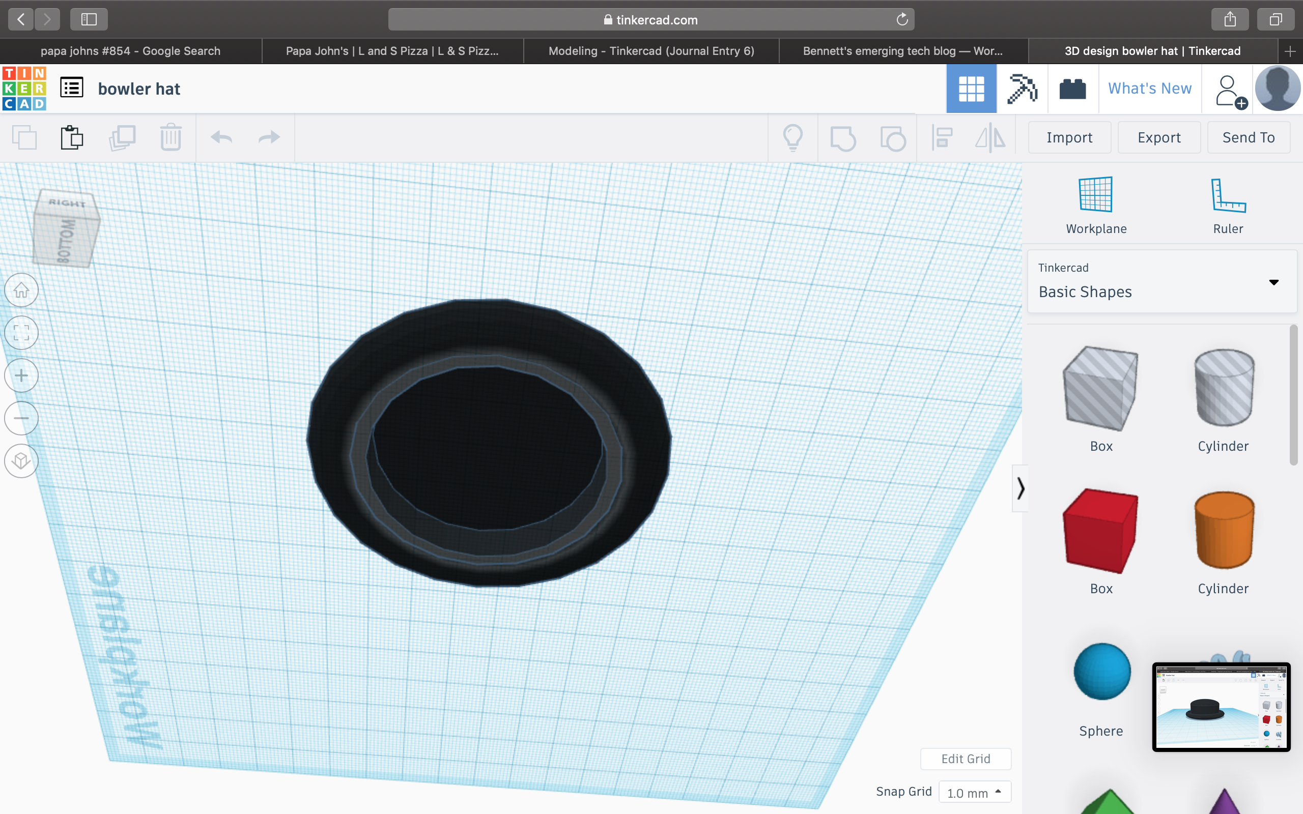
#5: Bowler hat
The bowler hat. A mysterious piece of fabric some wear to look stylish? Or bowl in? Or protect themselves from the Sun? I’m not really sure because I’ve never worn one
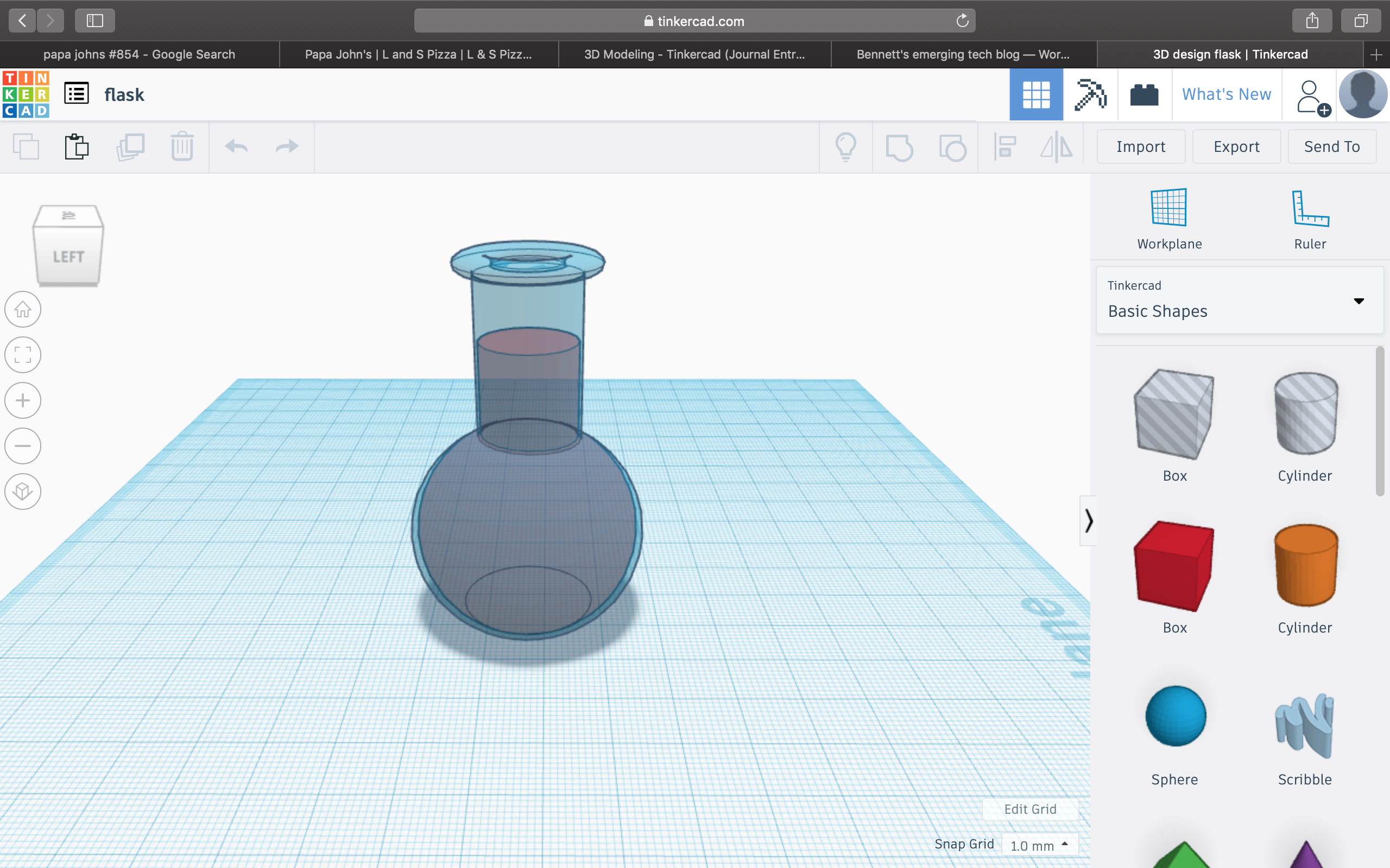
#6: Flask
A transparent flask which professor Von Hollen drinks from. Some suggest that the unknown liquid contained inside is just Mio, a water enhancer. However, I theorize that this liquid is some sort of radioactive fluid which gives one supernatural capabilities.
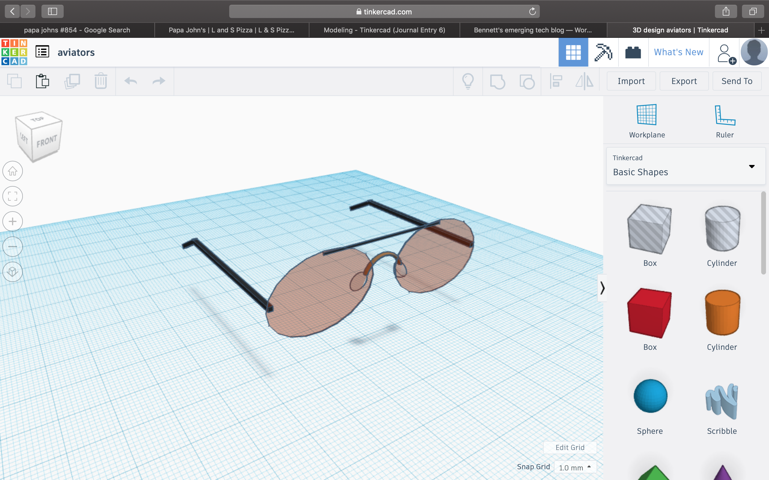
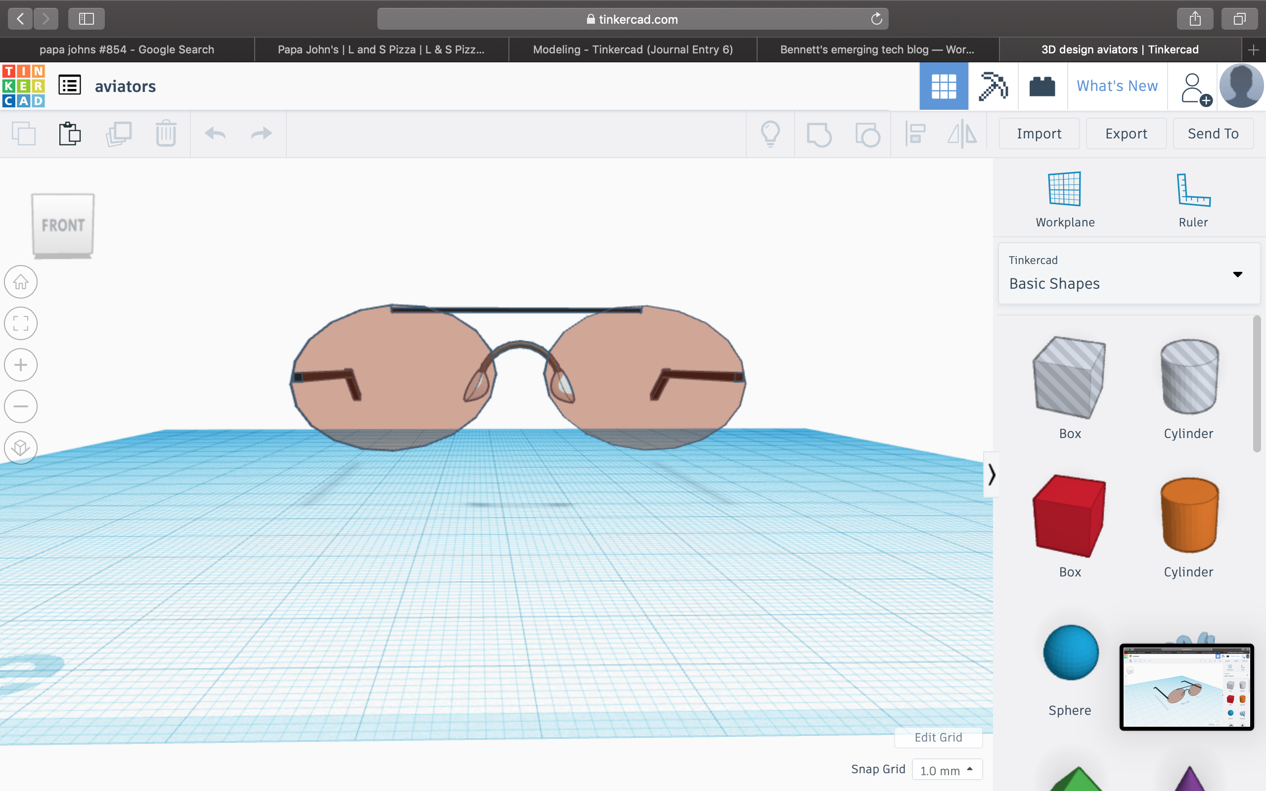
#7: Aviators
Finally, the most difficult of all of the models, aviators. Only someone who has achieved mastery of the Tinkercad program could construct such a model. And I did.
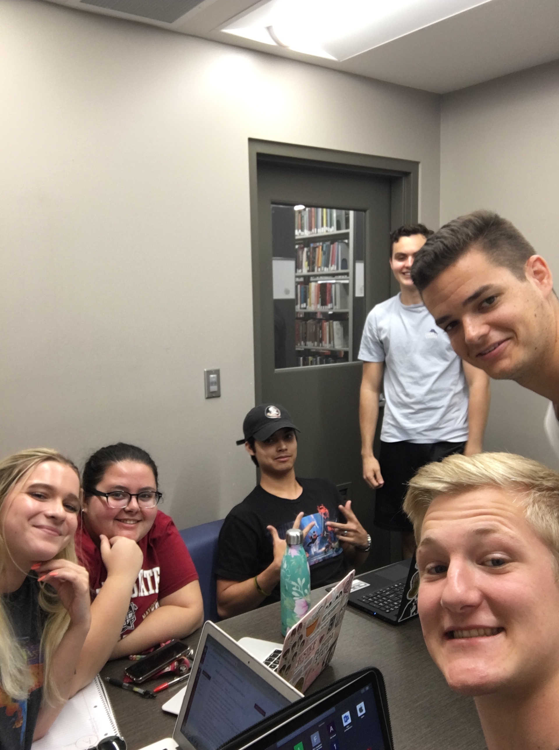
For this project, my group and I decided to make a “create your own story” app with different choices for each event which can lead to many different outcomes. The contributions I have made so far have been taking notes on what we accomplish when our group meets, helping find media online for our slides, and coming up with ideas for mini games within our storyline which will make playing the app more interactive and fun. One thing I have noticed about this project is it is a little difficult for everyone to be busy when our group meets since we can only pull up app inventor on one of our laptops and essentially, our storyline has already been written. Another problem we ran into was that app inventor only allows 10 screens to be made and our story requires 25 screen so we are currently looking for a way to create multiple screens within a screen to get around that roadblock. Aside from those issues, my group has been great to work with. Everyone really tries to contribute within the group and no one has missed a group meeting so far. We have met twice outside of class for this project, once on Tuesday 6/4 in Strozier and once on Monday 6/3 in the innovation hub. So far, we have only included pictures in our app to guide the user with our choices, but when we are able to add more screens I came up with an idea of an interactive mini game where a ball is dragged through a maze and if the ball touches the walls of the maze, you have to restart. (this game would be imitating re-circuiting a robot).
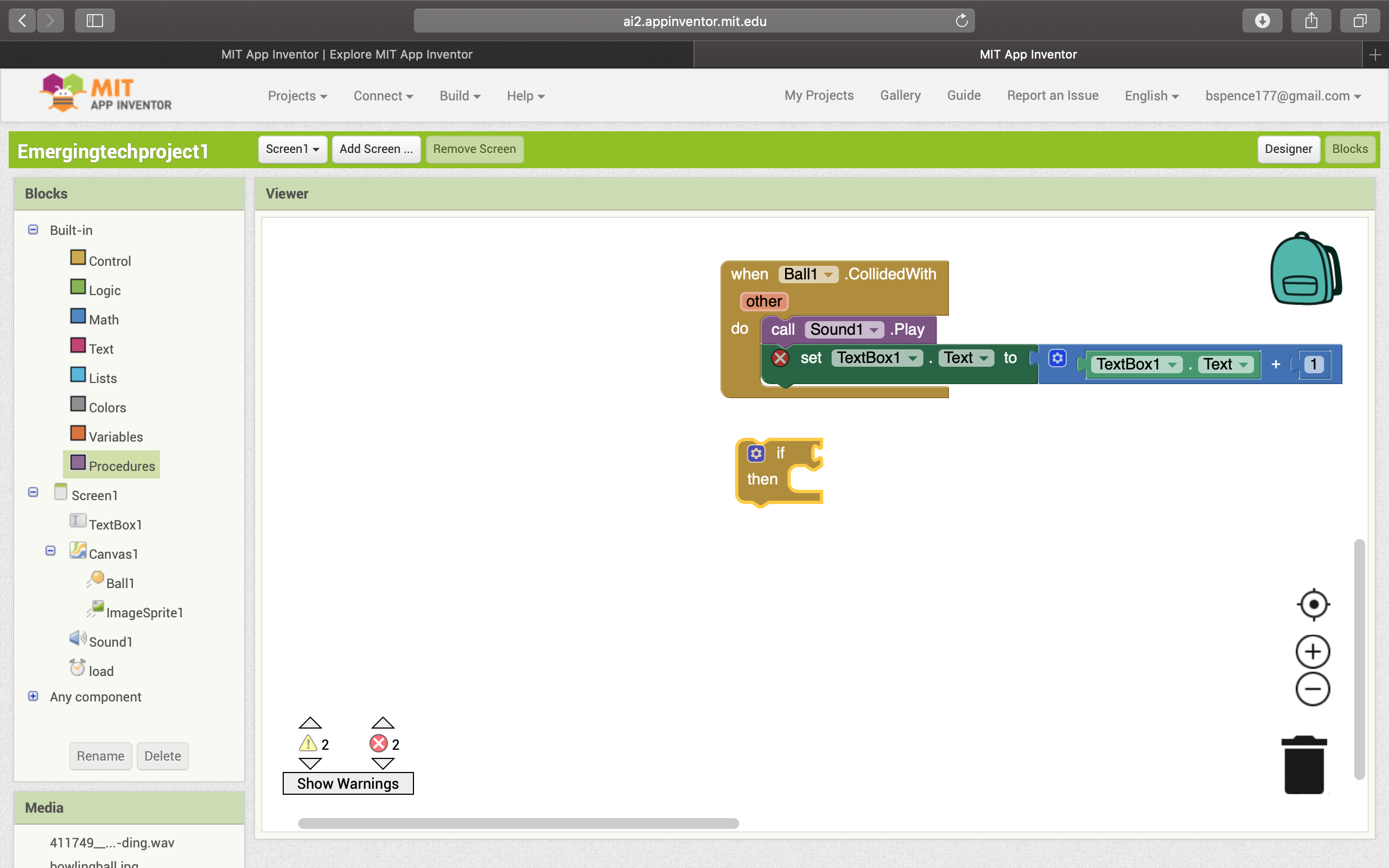
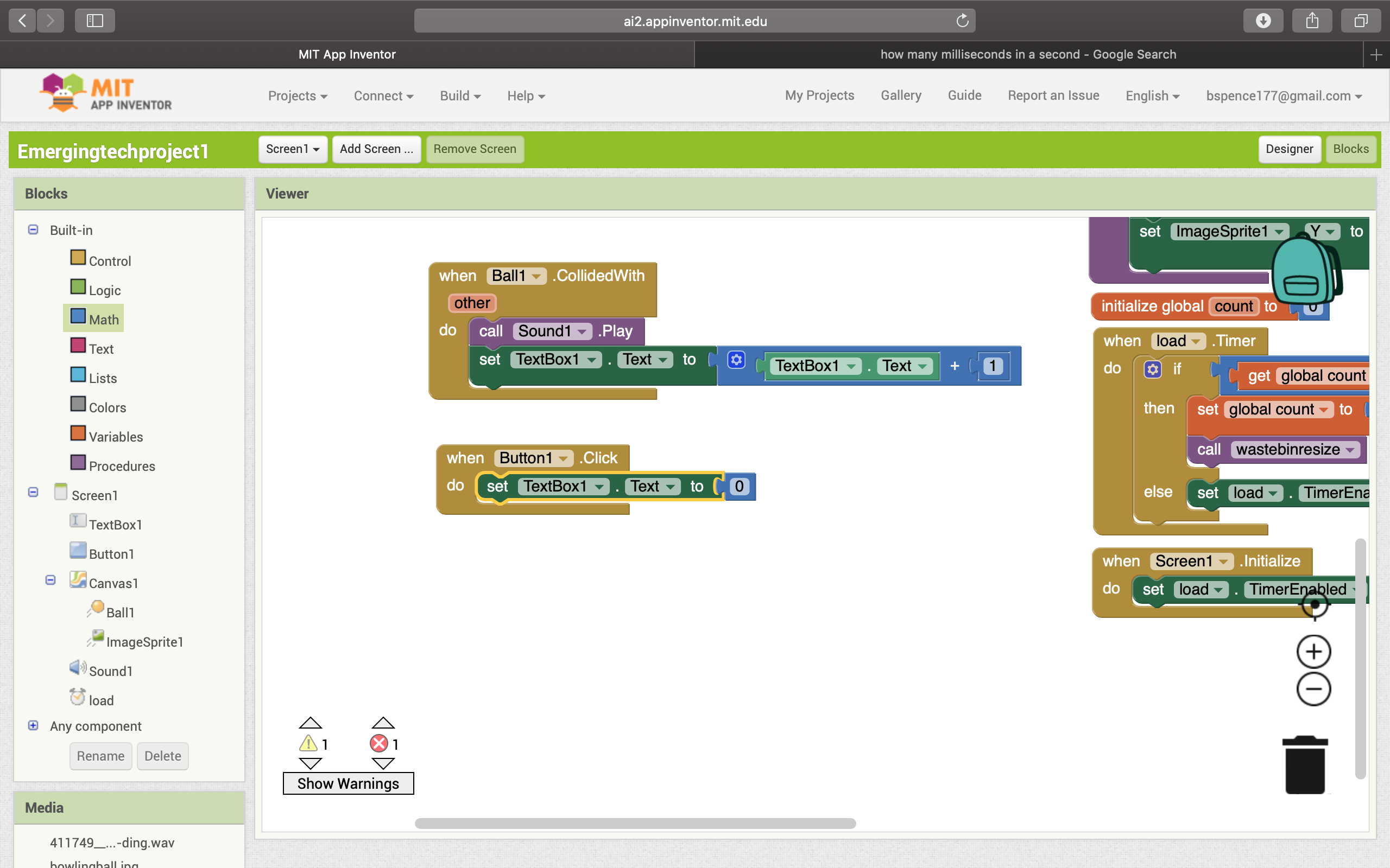
Working with app inventor has been an interesting process. At first, I had no idea where to start/what to do so I watched some youtube videos to learn the basics and get some ideas. At first, I wanted to make a bowling game where I would be able to flick a ball into a group of pins and make a sound. After playing around with that idea, I decided instead to make a game where a ball drops into a waste bin and makes a sound. After randomizing where the ball would drop every time and adjusting the speed of the ball, I added the waste bin. When I added the waste bin, the properties of the photo were large and although I added a formula to resize the waste bin, every time I reopened the emulator, the waste bin would appear big and out of place again. I looked up how to get around this and ended up adding a clock to rerun the properties I wanted of the waste bin 3 times every time the screen initialized which ended up fixing the problem. I then added a formula which allowed me to drag the waste bin around the screen. I also added a formula which called for a “ding” noise to be made when the waste bin collided with the ball. The final thing I wanted to add to make my game complete was a point system which added a point every time the waste bin collided with the ball. At this point in the process I ran into my final problem. I wanted to figure out how to reset the points to zero every time the waste bin did not catch the ball.
This formula allows the “ding” sound to be played and the score to go up simultaneously when the waste bin collides with the ball.
I could have made this work if I was able to fit the “when ball collided with” statement into an if then statement to read, “if ball collided with waste bin, then increase textbook number + 1, and then add an else statement to reset the textbook number (score) back to 0 if this condition was not met. Unfortunately, the top statement would not fit in the if then box so I could not take this route. After exploring many other routes, I decided to simply add a reset button which reset the score to 0 and used the following formula:
When button1 click do set textbook text to 0
So, because of this issue, you can get an unlimitedly high score until the reset button is pressed. All in all, I think my game turned out well and was definitely a learning experience for me as I have never done anything of this nature before.